Leave A Message
If you are interested in our products and want to know more details,please leave a message here,we will reply you as soon as we can.

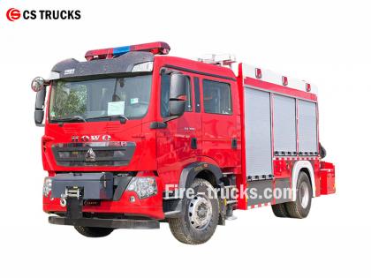
The Isuzu Fire Truck 4HK1-TC Engine Maintenance Manual, also called Engine repair manual of Isuzu fire tender or Engineer book of Isuzu fire fighting vehicle.
The Isuzu Fire Truck 4HK1-TC engine is a high-performance diesel engine widely used in fire trucks, known for its reliability, durability and high efficiency. In order to ensure the long-term stable operation of the engine, regular maintenance and repair are essential. This article will briefly introduce the main contents of the Isuzu Fire Truck 4HK1-TC Engine Maintenance Manual to help maintenance personnel better understand and operate.
1. Engine Overview
The 4HK1-TC engine is a 4-cylinder inline turbocharged diesel engine with a displacement of 5.2 liters and a maximum power of 190 horsepower. The engine uses an advanced common rail fuel injection system and an electronic control unit (ECU) to achieve higher fuel efficiency and lower emissions.
2. Daily Maintenance
Daily maintenance is the basis for ensuring the normal operation of the engine. The maintenance manual lists in detail the items for daily inspection, including oil and coolant level inspection, air filter cleaning or replacement, fuel filter replacement, etc. In addition, the manual also provides recommendations for regular replacement of engine oil and oil filter, usually every 5,000 kilometers or every 6 months.
3. Fault Diagnosis
The maintenance manual contains a detailed fault diagnosis process to help maintenance personnel quickly locate and solve problems. The manual lists common fault codes and their meanings, and provides corresponding solutions. For example, if the engine is underpowered, the manual will guide maintenance personnel to check the fuel system, turbocharger and exhaust system, etc.
4. Overhaul and Parts Replacement
For engines that need overhaul or replacement of parts, the maintenance manual provides detailed steps and precautions. For example, when replacing key components such as piston rings, valve guides and bearings, the manual will detail the steps for removal and installation, as well as the required tools and torque specifications.
5. Safety Precautions
The maintenance manual places special emphasis on the importance of safe operation. Before performing any maintenance operations, you must ensure that the engine has been completely cooled and the power supply is disconnected. In addition, the manual also provides recommendations for the use of personal protective equipment, such as gloves, goggles and protective clothing.
Section 1A
Engine control system
Table of Contents
Page
Engine control system
Precautions
Function and working principle
Parts configuration diagram
Circuit diagram
How to diagnose the fault
Fault diagnosis operation procedures through fault diagnostic meter
Functional check overview
Inquiry
Engine control system check
Fault diagnostic meter data list
Fault diagnostic meter data list contents
Fault diagnostic meter output
Fault diagnostic meter start failure
Fault diagnostic meter communication failure (reference)
Communication failure with ECM (reference)
Starting system confirmation
Engine MIL illuminating electrical circuit system confirmation
Engine MIL blinking electrical circuit system confirmation
Exhaust gas recirculation (EGR) control system inspection
Warming-up control system inspection
Exhaust brake/ air inlet restriction control system inspection
Diagnostic trouble code (DTC) overview
DTC P0016 (Flash code 16)
DTC P0087 (Flash code 225)
DTC P0088 (Flash code 118)
DTC P0089 (Flash code 151)
DTC P0091, P0092 (Flash code 247)
DTC P0093 (Flash code 227)
DTC P0107, P0108 (Flash code 32)
DTC P0112, P0113 (Flash code 22)
DTC P0117, P0118 (Flash code 23)
DTC P0122, P0123 (Flash code 43)
DTC P0182, P0183 (Flash code 211)
DTC P0192, P0193 (Flash code 245)
DTC P0201, P0202, P0203, P0204 (Flash code 271,272,273,274)................................................... 1A-157
DTC P0217 (Flash code 542)...................................................................................................... 1A-170
DTC P0219 (Flash code 543)...................................................................................................... 1A-172
DTC P0234 (Flash code 42)........................................................................................................ 1A-175
DTC P0299 (Flash code 65)........................................................................................................ 1A-178
DTC P0335 (Flash code 15)........................................................................................................ 1A-182
DTC P0336 (Flash code 15)........................................................................................................ 1A-187
DTC P0340 (Flash code 14)........................................................................................................ 1A-190
DTC P0341 (Flash code 14)........................................................................................................ 1A-195
DTC P0380 (Flash code 66)........................................................................................................ 1A-198
DTC P0381 (Flash code 67)........................................................................................................ 1A-201
DTC P0404 (Flash code 45)........................................................................................................ 1A-205
DTC P0409 (Flash code 44)........................................................................................................ 1A-208
DTC P0477, P0478 (Flash code 46)............................................................................................. 1A-212
DTC P0500 (Flash code 25)........................................................................................................ 1A-216
DTC P0502, P0503 (Flash code 25)............................................................................................. 1A-218
DTC P0563 (Flash code 35)........................................................................................................ 1A-223
DTC P0601 (Flash code 53)........................................................................................................ 1A-225
DTC P0602 (Flash code 154)...................................................................................................... 1A-226
DTC P0604, P0606, P060B (Flash codes 153, 51, 36).................................................................... 1A-228
DTC P0641 (Flash code 55)........................................................................................................ 1A-230
DTC P0650 (Flash code 77)........................................................................................................ 1A-233
DTC P0651 (Flash code 56)........................................................................................................ 1A-237
DTC P0685, P0687 (Flash code 416)........................................................................................... 1A-241
DTC P0697 (Flash code 57)........................................................................................................ 1A-245
DTC P1093 (Flash code 227)...................................................................................................... 1A-248
DTC P1261, P1262 (Flash code 34)............................................................................................. 1A-253
DTC P1404 (Flash code 45)........................................................................................................ 1A-255
DTC P1621 (Flash code 54)........................................................................................................ 1A-257
DTC P2122, P2123 (Flash code 121)........................................................................................... 1A-258
DTC P2127, P2128 (Flash code 122)........................................................................................... 1A-264
DTC P2138 (Flash code 124)...................................................................................................... 1A-270
DTC P2146, P2149 (Flash code 158)........................................................................................... 1A-273
DTC P2228, P2229 (Flash code 71)............................................................................................. 1A-279
DTC P253A (Flash code 28)....................................................................................................... 1A-284
DTC P256A (Flash code 31)....................................................................................................... 1A-287
DTC U0073 (Flash code 84)....................................................................................................... 1A-291
Symptom diagnosis................................................................................................................... 1A-296
Phenomena: Intermittence.......................................................................................................... 1A-297
Symptom: Difficult starting........................................................................................................ 1A-300
Phenomena: Surge, unsteady idling or engine stalling.................................................................... 1A-303
Phenomena: High idling speed.................................................................................................... 1A-306
Symptom: Emergency stop......................................................................................................... 1A-307
Symptom: Emergency change..................................................................................................... 1A-309
Symptom: Under-power, acceleration failure or response lag........................................................... 1A-311
Phenomena: Intermitted operation, acceleration failure................................................................... 1A-314
Symptom: Combustion noise...................................................................................................... 1A-316
Symptom: Fuel economical efficiency low.................................................................................... 1A-317
Phenomena: black smoke from exhaust gas................................................................................... 1A-319
Symptom: White smoke from exhaust gas.................................................................................. 1A-321
Main sensor parameters.............................................................................................................. 1A-323
Special tools............................................................................................................................. 1A-325
Programme............................................................................................................................... 1A-326
Programming rule...................................................................................................................... 1A-326
Programme............................................................................................................................... 1A-326
Injection pump learning.............................................................................................................. 1A-328
Adjustment............................................................................................................................... 1A-328
Use of circuit testing tools
In the case of diagnosis according to the diagnostics program, do not use the test lamp for the power train electrical system diagnosis unless otherwise specified. In case the probe terminal will be used for the diagnostic program, please use the terminal testing adapter kit 5-8840-2835-0.
Market available electrical component
The market available electrical components mean the electrical components purchased from the market to install to the vehicle. Since these components are not taken into account during the vehicle design stage, pay attention to them when using these components.
Caution:
The market available electrical component power and ground must be connected to the circuit unconcerned to the electrical control system circuit.
Though the market available electrical components can be used, these may cause the functional fault of the electrical control system in some cases. It includes the devices not connected to the electrical system, for example, the mobile telephone, radio. Therefore, in the power train diagnosis, first check whether such market available electrical components are installed. If so, remove them from the vehicle. If the fault still exists after the componment removal, follow the general flow for diagnosis.
Damage due to ESD
Since the electronic parts in the electrical control system can work under the extremely low voltage, these are easy to be damaged due to ESD. Some electronic parts will be damaged by the static electricity below 100V that not appreciable to the human. The human appreciable ESD requires 4000V voltage. In many cases, the human will carry the static electricity, in which the friction and induction electrification is the most common.
● When the human moves side to side on the seat, it will generate the frictional electrification.
● When the human wearing the insulated shoes is near the highly electrified object, the electrostatic induction will occur at the moment of human touching the ground. The human will be electrified when the charges of the same polarity meet the charges of opposite polarity. Since the static electricity will cause damage, carefully handle the electronic parts and test them.
Caution:
Observe the following rules to prevent the damage due to ESD:
● Do not touch the ECM terminal contact pins and electronic parts soldered to ECM circuit back plate.
● Do not unpack the parks unless the preparation of part installation is finished.
● Connect the package and vehicle normal ground before taking the parts out of the package.
● If moving side to side on the seat, or sitting from standing posture or operating the part while moving in a certain distance, ensure to touch the normal ground before installing the part.
Function and working principle
Engine control (common rail) system
System overview and details
The engine control system means the electrical control system to control the engine to the optimal combustion state according to the driving condition. It consists of the following parts:
● Electronically controlled fuel injection system (common rail type)
● EGR
Besides, the engine control system includes the following system control functions.
● Warming-up control system
● Engine rotary output
● Communication and self-diagnosis function

Electronically controlled fuel injection system (common rail type)
The common rail system is provided with the pressure chamber and injector. The pressure chamber is designed to store the pressurized fuel and called the common rail; the injector is provided with the electronic control solenoid valve to inject the pressurized fuel to the combustion chamber. Since the injection control (the injection pressure, injection rate and injection time) is controlled by ECM, the common rail system allows the independent control of the engine speed and load. Even if the engine speed is low, the stable injection pressure can be maintained, which will greatly reduce the specific black smoke upon the diesel engine start and acceleration. Through this control, the exhaust gas will become clean, the exhaust volume will be less and the output will be higher.
Injection volume control
It controls the injector winding according to the signal obtained from the engine speed and accelerator pedal opening and consequently controls the fuel injection volume to achieve the best volume.
Injection pressure control
To allow the high pressure injection even if the engine speed is low, the common rail inside fuel pressure should be controlled. Work out the appropriate pressure in the common rail according to the engine speed and fuel injection volume, discharge the proper amount of fuel through the control injection pump and feed it to the common rail under pressure.
Injection time control
It substitutes the timing function and works out the appropriate fuel injection time according to the engine speed and injection volume and then controls the injector.
Injection rate control
To enhance the cylinder combustion efficiency, inject (pre-injection) a little fuel for ignition. After the ignition, carry out the second time injection (main injection). Control the injection time and injection volume through the injector (the injector coil).


Fuel System
The common rail system consists of 2 fuel pressure systems.
● Low pressure inlet line: between the fuel tank and injection pump
● High pressure line: between the injection pump and injector
The fuel is sucked into injection pump from the fuel tank and boosted in the pump to supply to the common rail. At this point, the signal from ECM controls the suction control valve (the common rail pressure regulator) to control the fuel volume supplied to the common rail.
Fuel system diagram

|
Key 1. Common Rail 2. Pressure limiting valve 3. Injector return pipe 4. Injector 5. Fuel return pipe 6. Fuel supply pipe |
7. Fuel tank 8. Breather valve 9. Starter pump 10. Fuel filter (with oil-water separator) 11. Return valve 12. Fuel injection pump |
EGR (Exhaust gas recirculation)
Egr system recycles a part of exhaust gas to the intake manifold and consequently reduces the nitrogen oxides (NOx) emission. Through the EGR system, the driving operability and exhaust gas emission reduction can be achieved. The control current from the EGR controls the solenoid valve to work and consequently control the EGR valve lift. In addition, this system detects the actual valve lift with the EGR position sensor to realize the fine control over the EGR.
EGR will start working when the engine speed, engine coolant temperature, intake temperature and barometric pressure conditions are met. Then it will work out the valve opening according to the engine speed and target fuel injection volume. Basing on the calculated valve opening, it decides the solenoid valve drive load and then drives the valve. The air intake throttle will be shut down during EGR operation to enable the intake manifold inside pressure to reach the target value.
|
|
|
|

|
Key 1. ECM 2. EGR position sensor 3. EGR valve 4. EGR cooler |
5. Intake throttle valve
|
Warming-up control
Warming-up control system
The warming-up control system is designed to ease the engine start at low temperature and reduce the white smoke and noise. With the starter switch active, ECM detects the engine coolant temperature according to the signal from the engine coolant temperature (ECT) sensor to adjust the warming-up time and achieve the appropriate starting conditions for the engine. In addition, the residual heat of warming-up can maintain the idling stable. ECM decides the warming-up time according to the engine coolant temperature to drive the warming-up relay and indicator lamp to work.

Overview of exhaust brake control
The exhaust brake exhaust pipe is provided with valve inside. Closing the valve can increase the exhaust stroke resistance and enhance the engine brake effect. The exhaust brake valve works according to the vacuum pressure. The exhaust brake vacuum pressure is controlled by the open and close of solenoid valve. ECM will enable the solenoid valve if the engine speed is above 575rpm and all the exhaust brake operating conditions are met.
Exhaust brake operating conditions
● Exhaust brake switch on
● Accelerator pedal not depressed
● Not detecting accelerator pedal position (APP) sensor abnormal, exhaust brake circuit abnormal, clutch switch abnormal, APP sensor switch abnormal, A/D switch abnormal etc.
● Clutch pedal not depressed
● System voltage above 24V
● Vehicle speed exceeding specified range
ECM
Overview of ECM

ECM monitors the information from every sensor all the time to control the power train. ECM performs system diagnostic function to detect the system operation problem, remind the driver through the engine MIL and record DTC at the same time. DTC identifies the trouble zone to help the maintenance man.
ECM functions
ECM exports 5V voltage to power various sensors and switches. However, since the power is supplied by the ECM resistance, the test lamp connected to the circuit will not be on even if the resistance is very high. In some case, the common voltmeter cannot display the correct reading since its resistance is too low. To display the correct reading, ensure to use the digital multimeter of 10MΩ input impedance at least (5-8840-2691-0). ECM controls the ground circuit or power circuit through the transistor or other unit and consequently controls the output circuit.
ECM and composition parts
ECM can achieve the high steerability and fuel efficiency while maintaining the specified waste gas exhaust. ECM monitors the engine and vehicle performance through the crankshaft position (CKP) sensor and vehicle speed sensor (VSS) etc.
ECM voltage description
ECM applies the standard voltage to each switch and sensor. This is because the ECM resistance is very high while the voltage applied to the circuit is low. The test lamp will not illuminate even if connected in the circuit. Since the input impedance of voltmeter generally used by the maintenance man is very low, sometimes the voltmeter cannot display the correct reading. In such a case, use digital multimeter of 10MΩ input impedance (5- 8840 -2691-0) to get the correct voltage reading.
The ECM input/output unit is equipped with analog-digital converter, signal damping, counter and special actuator. ECM can control most composition parts through the electronic switch.
EEPROM
EEPROM is permanent storage chip soldered to the ECM back plate. To control the power train, ECM transmits the necessary program and calibration message to EEPROM.
Different from ROM, EEPROM cannot be replaced. If EEPROM is detected abnormal, replace the ECM directly.
Considerations for ECM repair
ECM can withstand the general current relevant to vehicle driving. Do not allow the circuit overload. During the open circuit and short circuit test, do not connect the ECM circuit to the ground wire or apply the voltage unless otherwise specified. For such circuit tests, ensure to use the digital multimeter (5-8840-2691-0).

The injection pump is the core part of common rail electronic fuel injection system. The injection pump is installed to the engine front. The common rail pressure regulator and fuel temperature (FT) sensor are the composition parts of the injection pump.
The fuel is fed to the injection pump from the fuel tank through the inside supply pump (rotor type). The supply pump feeds the fuel into 2 plunger compartments in the injection pump. The fuel fed to the plunger compartment is regulated by the common rail pressure regulator. The common rail pressure regulator is only controlled by the ECM supply current. The fuel flow will reach the maximum if no current is fed to the solenoid valve. Contrarily, the fuel will stop flowing when the solenoid valve current reaches the maximum. As the engine rotates, the two plungers build high pressure in the common rail. It controls the common rail pressure regulator according to the ECM signal and consequently controls the fuel volume and pressure to the common rail. In this way, the optimal operating state can be realized to enhance the fuel economical efficiency and reduce the NOx emission.

Key
1. Fuel temperature (FT) sensor
2. Suction control valve (common rail pressure regulator)
Suction control valve (common rail pressure regulator)
ECM controls the load factor of common rail pressure regulator (the power-on time of common rail pressure regulator) to regulate the fuel volume fed to the high pressure plunger. To achieve the desired rail pressure, feed the proper amount of fuel to reduce the drive load of the injection pump. When the current is fed to the common rail pressure regulator, the variable electromotive force corresponding to the load factor will be generated to vary the fuel line opening and consequently adjust the fuel volume. When the common rail pressure regulator is switched off, the retracting spring will retract, the fuel line will completely open and the fuel will flow to the plunger (the maximum intake and maximum discharge). With the common rail pressure regulator open, the fuel line will close (normally open) under the function of the retracting spring. Through the open and close of common rail pressure regulator, the fuel corresponding to the working load rate will be supplied and then discharged from the plunger.
Fuel temperature (FT) sensor
FT sensor is installed to the injection pump and the thermistor changes the resistance along with the temperature variation. The resistance will be low if the fuel temperature is high and high if the fuel temperature is low. ECM applies 5V voltage to FT sensor through the load resistor and works out the fuel temperature according to the voltage variation to control the injection pump. The voltage will be low if the resistance is low (the temperature is high) and high if the resistance is high (the temperature is low).
Common rail

Key
1. Pressure limiting valve
2. Common rail pressure sensor
Due to the common rail type electrical control fuel injection system, the common rail is provided between the injection pump and injector to store the high pressure fuel. The pressure sensor and pressure limiting valve are installed on the common rail. The pressure sensor detects the fuel pressure in the common rail and transmits the signal to ECM. Basing on this signal, ECM controls the fuel pressure in the common rail with the injection pump common rail pressure regulator. If the common rail inside fuel pressure is too high, the pressure limiting valve will open to release the pressure.
Common rail pressure sensor
The common rail pressure sensor is installed to the common rail to detect the fuel pressure in the rail and convert the pressure into voltage signal. The higher the pressure, the higher the voltage; the lower the pressure, the lower the voltage. ECM works out the actual common rail pressure (the fuel pressure) according to the voltage signal from the sensor to control the fuel injection.
Pressure limiting valve

Key
1. Valve
2. Valve body
3. Valve guide
4. Spring
5. Housing
6. Fuel inlet
7. Fuel outlet
In the case of abnormal high pressure, the pressure limiting valve will open to release the pressure. The valve will open when the common rail inside pressure exceeds 220MPa and close when the pressure is below 50MPa. The fuel discharged from the pressure limiting valve will flow to the fuel tank.
Injector

Key
1. Wiring bolt
2. Return to the pipeline installation department
3. O-ring
4. Injection pipe installation part
5. Identification marking
6. Injector ID code
Compared to the earlier injection nozzle, the electrical control injector controlled by ECM is provided with command piston and solenoid valve. This information is recorded in the ID code (24 English numbers) to display the injector characteristics. This system controls the injection volume to achieve the optimal effect with the injector flow information (ID code). When a new injector is installed to the vehicle, ensure to enter ID code in ECM.
To enhance the injection volume accuracy, use the 2D bar code or ID code on the injector. With the code, the decentralized control injection volume can be achieved on each pressure zone to enhance the combustion rate, reduce the exhaust and provide the stable output .

● Without injection
If ECM does not power the solenoid valve through the two-way valve (TWV), it will close the outlet throttling orifice with the piston force. At this point, the fuel pressure applied to the nozzle front end will be balance with the fuel pressure applied to control room through the inlet. In this pressure balance state, the sum of pressure applied to command piston and nozzle piston gravity will be higher than the pressure applied to the nozzle front end. Therefore, the nozzle will be pushed down to close the injection hole.
● Injection
If ECM powers the solenoid valve, TWV will be pulled to open the outlet throttling orifice and the fuel will flow to the oil return port. At this point, the nozzle and command piston are lifted together with the pressure applied to the nozzle front end. Then the nozzle injection hole will open to inject the fuel.
● Injection end
When the ECM stops powering the solenoid valve, TWV will fall and the outlet opening part will close. At this point, the fuel cannot flow to the return port from the control room and the fuel pressure inside will rise quickly. Then the nozzle will be depressed by the command piston to close the injection port and then the fuel injection will stop.
Engine coolant temperature (ECT) sensor

ECT sensor is installed near the thermostat shell and the thermistor changes the resistance along with the temperature variation. The resistance will be lower if the engine coolant temperature is high and high if the engine coolant temperature is low. ECM applies 5V voltage to ECT sensor through the load resistor and works out the engine coolant temperature according to the voltage variation to control the fuel injection. The voltage will be low if the resistance is low (the temperature is high) and high if the resistance is high (the temperature is low).
Camshaft position (CMP) sensor

Key
1. Camshaft gear
2. Rotation direction
3. Camshaft position (CMP) sensor
The camshaft position (CMP) sensor is installed to the cylinder head rear section. The cam section of the camshaft generates the CMP signal when passing through the sensor. ECM determines the cylinder conditions and crankshaft angle according to the CMP signal and CKP sensor input CKP signal to control the fuel injection and calculate the engine speed. Though these controls base on CKP signal in general, they will work according to the CMP signal in the case of CKP sensor abnormal.
Crankshaft position (CKP) sensor

Key
1. Crankshaft position (CKP) sensor
The CKP sensor is installed to the flywheel housing. When the flywheel hole passes through the sensor, it will generate CKP signal. ECM determines the cylinder conditions and camshaft angle according to the CKP signal and CMP sensor input CMP signal to control the fuel injection and calculate the engine speed. Though these controls base on CKP signal in general, they will work according to the CMP signal in the case of CKP sensor abnormal.
Accelerator pedal position (APP) sensor 1

APP sensor is installed to the accelerator pedal control bracket. This sensor consists 2 sensors in one shell. ECM determines the acceleration and deceleration target value with the APP sensor. APP sensor is pin hole 1C type sensor. The signal voltage changes along with the accelerator pedal angle variation proportionably. APP sensor 1 signal voltage is low at in the early stage and increases as the pedal depressed. APP sensor 2 signal voltage is high at in the early stage and decreases as the pedal depressed.
Vehicle speed sensor

The vehicle speed sensor (VSS) is installed to the transmission. The vehicle speed sensor is equipped with HALL effect circuit. The magnet and output shaft generate the magnetic field when rotating together and then generate the pulse signal through the interaction with the magnetic field.
Atmospheric pressure sensor

The barometric pressure sensor is installed to the dashboard and changes the signal voltage along with the pressure. ECM detects the low signal voltage when the pressure is low in the high elevation area; contrarily, it detects the high signal voltage when the pressure is high. With these voltage signals, ECM can regulate the fuel injection volume and injection time to correct the elevation.
Intake air temperature (IAT) sensor

Intake air temperature (IAT) sensor
IAT sensor is installed to the guide tube between the air filter and turbocharger. When the IAT sensor temperature is low, the sensor resistance will be high. When the air temperature increases, the sensor resistance will be lower. When the sensor resistance is high, ECM will detect the high voltage on the signal circuit. When the sensor resistance is low, ECM will detect the low voltage on the signal circuit.
EGR valve

EGR valve is installed to the intake manifold. ECM controls the opening of EGR valve according to the engine operating state. According to the duty ratio signal from ECM, it controls the magnetic coil in EGR valve. Through the position sensor, it can detect the EGR valve opening. The position sensor is provided with 3 sensors in EGR valve to detect 3 locations respectively. Position sensors 1, 2, 3 are pin hole 1C type. The position sensor exports the valve open/close state in form of signal, which is in proportion with the variation of EGR valve opening.
Intake pressure sensor

The intake air pressure sensor is installed to the air inlet duct to detect the intake air pressure and convert the pressure into voltage signal. ECM detects high voltage when the pressure is high. It detects low voltage when the pressure is low. ECM works out the intake air pressure according to the voltage signal from the sensor to control the fuel injection and turbocharger.
Engine malfunction warning lamp

The engine malfunction warning lamp is installed inside the instrument to remind the driver of the engine or related system abnormal. When ECM detects abnormal through the self-diagnosis function, the engine malfunction warning lamp will be on. Short the data link connector (DLC) terminals to make the engine malfunction warning lamp blink. Then the DTC detecting state can be confirmed.
Data Link Connector (DLC)

DLC is installed to the lower left of the driver and it is the communication connector for the fault diagnostic meter and each control unit. It is provided with the diagnosis switch function. Through the short-circuit of DLC, it can enable the diagnosis switch.
Engine composition parts layout
(1/2)

|
Key 1. Engine coolant temperature (ECT) sensor 2. Injector (in cylinder head cover) 3. Injector harness middle joint |
4. EGR valve 5. Common rail pressure sensor 6. Pressure limiting valve 7. Suction control valve (common rail pressure regulator) 8. Fuel temperature (FT) sensor |
(2/2)

Key
1. Crankshaft position (CKP) sensor
2. Cam position (CMP) sensor
Engine composition parts layout 1

Key
1. ECM
2. Terminal resistor
Engine composition parts layout 3

|
Key 1. Ventilation bar rack 2. Glove box (small) 3. Heating unit, defroster control panel, A/C panel 4. Radio cassette or CD player 5. Glove box (large) 6. Windshield wiper, washer switch lever, exhaust auxiliary brake switch lever 7. Cluster switch lever 8. Steering wheel adjustment locking lever 9. Hazard warning flash lamp switch |
10. Cigarette lighter 11. Card case 12. Hook 13. Concealed type cup holder 14. Fuse box cover plate 15. Toolbox |
Circuit diagram sketch (1/2)

(2/2)
|
|
|
|
|
|
|
|
|
|
|
|
|
|
|
|
|
|
|
|
|
|

Terminal arrangement
|

ECM terminal end view
ECM

|
Joint SN |
J-14 |
|
|
Joint color |
Black |
|
|
Test adapter SN |
J-35616-64A |
|
|
Port No. |
Wire color |
Port function |
|
1 |
Black |
ECM signal ground |
|
2 |
Red |
Battery voltage |
|
3 |
Black |
ECM signal ground |
|
4 |
Black |
ECM signal ground |
|
5 |
Red |
Power voltage |
|
6 |
Blue/Red |
Malfunction Indicator Lamp (MIL) Control |
|
7 |
Blue/Pink |
Exhaust brake lamp control |
|
8 |
Light green |
Engine speed signal output to tachometer |
|
9 |
Light green/Black |
DPD indicator lamp control (Euro IV) |
|
10 |
Black/Red |
Glow plug relay control |
|
11 |
Orange/Blue |
Warming-up lamp control |
|
12 |
- |
Not used |
|
13 |
- |
Not used |
|
14 |
White/blue |
Starter on/off relay control |
|
15 |
Light green/white |
Exhaust brake solenoid valve control |
|
16 |
Blue/yellow |
Check oil residual volume warning lamp control |
|
Joint SN |
J-14 |
|
|
Joint color |
Black |
|
|
Test adapter SN |
J-35616-64A |
|
|
Port No. |
Wire color |
Port function |
|
17 |
Blue/Black |
SVS indicator lamp control (Euro IV) |
|
18 |
Blue/white |
CAN high signal input |
|
19 |
Yellow/green |
Vehicle speed sensor signal or electronic hydraulic control unit |
|
20 |
Black |
Accelerator pedal position sensor 1 shield ground |
|
21 |
Blue/Black |
ECM main relay control |
|
22 |
Green |
Air flow sensor signal low input (Euro IV) |
|
23 |
Yellow |
Air flow sensor 12V reference value (Euro IV) |
|
24 |
Yellow/Black |
Ignition voltage |
|
25 |
Red/white |
Cruise master switch signal |
|
26 |
Brown/yellow |
Clutch pedal switch signal |
|
27 |
- |
Not used |
|
28 |
- |
Not used |
|
29 |
- |
Not used |
|
30 |
- |
Not used |
|
31 |
- |
Not used |
|
32 |
- |
Not used |
|
33 |
Pink |
Refrigerating machine switch signal |
|
34 |
Green/Orange |
A/C switch signal |
|
35 |
Green/white |
Voltage dropping resistor |
|
36 |
- |
Not used |
|
37 |
Blue |
CAN lower signal input |
|
38 |
Light blue |
Keyword 2000 line data (non- Euro IV) |
|
39 |
Black |
Accelerator pedal position sensor 2 & air flow sensor (Euro IV) shield ground |
|
40 |
Blue/Black |
ECM main relay control |
|
41 |
Pink/black |
Accelerator pedal position sensor 1, idling sensor, PTO position sensor low input |
|
Joint SN |
J-14 |
|
|
Joint color |
Black |
|
|
Test adapter SN |
J-35616-64A |
|
|
Port No. |
Wire color |
Port function |
|
42 |
Red |
Accelerator pedal position sensor 1, idling sensor, PTO position sensor 5V power |
|
43 |
Black |
ECM signal ground |
|
44 |
Blue/Orange |
PTO Switch signal |
|
45 |
Light green/red |
Exhaust brake switch signal |
|
46 |
Red/white |
Ignition switch signal |
|
47 |
White /Red |
DPD switch signal (Euro IV) |
|
48 |
White/black |
Parking brake switch signal |
|
49 |
- |
Not used |
|
50 |
Black /blue |
Neutral switch signal |
|
51 |
Light green/blue |
Engine Preheat Switch signal |
|
52 |
Yellow |
Diagnosis switch |
|
53 |
Colorless/yellow |
Engine oil volume switch signal |
|
54 |
- |
Not used |
|
55 |
- |
Not used |
|
56 |
- |
Not used |
|
57 |
- |
Not used |
|
58 |
Blue/white |
CAN high signal input (Euro IV) |
|
59 |
Black |
Exhaust differential pressure sensor shield ground |
|
60 |
Black |
Accelerator pedal position sensor 2, barometric pressure sensor & intake air temperature sensor low input |
|
61 |
Red |
Accelerator pedal position sensor 2, barometric pressure sensor & air intake 5 V power |
|
62 |
Black |
ECM signal ground |
|
63 |
Blue/white |
Accelerator pedal position sensor 1 signal |
|
64 |
White |
Accelerator pedal position sensor signal |
|
65 |
|
Cruise control switch signal |
|
66 |
Blue/yellow |
Idling sensor signal |
|
67 |
Light green |
Exhaust differential pressure sensor signal (Euro IV) |
|
Joint SN |
J-14 |
|
|
Joint color |
Black |
|
|
Test adapter SN |
J-35616-64A |
|
|
Port No. |
Wire color |
Port function |
|
68 |
Black |
Optional (GND) |
|
69 |
Blue |
Air flow sensor signal (Euro IV) |
|
70 |
Brown |
PTO position sensor: |
|
71 |
Brown/green |
Barometric pressure sensor signal |
|
72 |
Red/Green |
Intake temperature sensor signal |
|
73 |
Yellow/Red |
Exhaust temperature sensor 1 signal (Euro IV) |
|
74 |
Red |
Exhaust temperature sensor 2 signal (Euro IV) |
|
75 |
- |
Not used |
|
76 |
- |
Not used |
|
77 |
- |
Not used |
|
78 |
Blue |
CAN low signal input (Euro IV or using boundary member) |
|
79 |
Black |
Exhaust differential pressure sensor, exhaust temperature sensor 1 & exhaust temperature sensor 2 low input (Euro IV) |
|
80 |
Blue/white |
Exhaust differential pressure sensor 5V power (Euro IV) |
|
81 |
Black |
ECM shell GND |


You may be interested in the following information
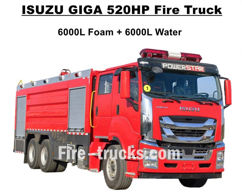
Top quality ISUZU GIGA fire fighting trucks export to West Africa Burkina Faso, which designed based on ISUZU GIGA VC66 heavy duty 6x4 truck chassis, adopt GIGA VC66 new cabin, standard air suspension seat and AC for comfortable driving. Truck mounted with Japanese ISUZU technology diesel engine 6WG1-TCG62 model, 520HP and emission can be 15681cc, matched working with FAST 12 shift manual gearbox, very lower fuel consumption, standard front 385/80R22.5 and rear 315/80R22.5, totally 10+1 units. Upper body kits including 6000L water tanker and 6000L foam tanker, all based on stainless steel #304 material, durable for long life service. Matched working with customized super powerful CB10/140 fire pump with efficiently flow rate 140L/s, matched with double fire pump on the top of tanker body kit, with model PL8/64 and efficiently flow rate 64L/s. Isuzu GIGA 520HP fire engine matched with all necessary fire fighting equipment, which is an idea fire engine for fire extinguishing and people rescue, and widely used in Burkina Faso market. ISUZU GIGA 520HP 14,000L Foam Tank Fire Truck CS TRUCKS factory is professional manufacturer in truck area,guarantee all products Brand-New and High-Quality. ISUZU Fire Truck Features: Name ISUZU GIGA 12000L foam pumper fire engine Cabin GIGA VC66 Engine 6WG1-TCG62 with 520HP and 15681cc emission Transmission FAST 12 shift Wheelbase 4600+1370mm Tire Front: 385/80R22.5 (2 pcs) Rear: 315/80R22.5 (8 pcs) Tanker 6000L foam tanker (Stainless Steel #304) 6000L water tanker (Stainless Steel #304) Fire Pump CB10/140 with flow rate 140L/s Fire Monitor Front One:PL8/64 with flow rate 64L/s Rear One:PL8/64 with flow rate 64L/s Equipment Full sets fire fighting equipment as customized How to Operate ISUZU Foam Tank Fire Engine: .
Details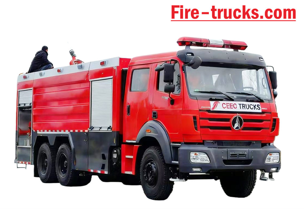
Beiben Fire Truck based on type II Beiben 2638 model 6*4 Left Hand Drive chassis, body capacity could up to 12,000Liters, including 10,000Liters water tanker and 2,000Liters foam tank, Beiben 2638 fire rescue truck equipped with XIONGZHEN CB10/60 fire pump and PL8/48 fire monitor, very convenient for daily use. Mainly used for firefighting project in any areas of need. The vehicle designed to fully rely on the advantages of the original of Beiben brand truck chassis, fully consider the product's convenience and reliability, also the newly designed chassis. The body material is international standard carbon steel with anti-corrosion painting and stainless steel, which can effective to avoid rusting and service for long life. The Beiben 6x4 Fire Truck equipped with Sandwich PTO, fire pump, fire monitor, crew room, hose box, pump room, dry powder tanker and nitrogen system, matched with pipeline hose reel, English version control box, inlet and outlet pipeline, rear climbing ladder, top pillow lamp, and all necessary firefighting equipment. Customized Double-row cabin with 2+4 seats nice driving feeling. Therefore, the vehicle is an ideal Fire Truck mainly for firefighting project.
Details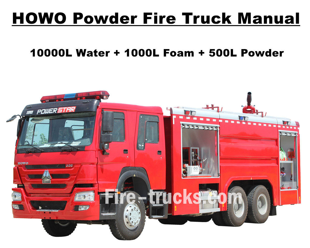
Africa Mauritania client purchased totally 4 units Sinotruk HOWO pumper fire engine from POWERSTAR TRUCKS and used in the the capital Nouakchott. Fire truck also can be called fire engine and fire pumper, which is a vehicle designed and manufactured to meet the needs of multiple fire extinguishing and people rescue project internationally. Customized double cabin row for firefighters carriage, various fire fighting equipment and tools for fire fighting, fire rescue, etc. To guarantee HOWO fire fighting trucks working more efficiently, we have customized to have truck equipped with Aluminum alloy ladders, water foam and dry powder fire agent and storage tankers, efficiently fire pump CB10/60 model matched with PL8/48 fire monitor, and efficiently jetting distance over 70m, fire fighting hose reel with gun for long distance fire extinguishing, breathing apparatus with mask, protective clothing, rescue tools, first-aid kit, etc. All service for HOWO fire trucks for efficiently and reliable working. To guarantee Mauritania clients use HOWO fire engine more easier and efficiently, all truck matched with full sets English version catalogue for service, including User's Manual for operation guidance, Truck Manual and Spare Parts Manual for usage and maintenance. SINOTRUK HOWO 14,000L Powder Pumper Fire Truck POWERSTAR factory is professional manufacturer in truck area,guarantee all products Brand-New and High-Quality. »Ⅰ. HOWO Fire Truck Advantages : ★ 247KW / 336HP powerful WEICHAI diesel engine, 100,000 Km without prblem. ★ SINOTRUK HOWO classical HW76 cabin, Europen design ★ Mounted CB10/60 fire pump, 60L/s flow rate, super reliable ★ Top mounted PL8/48 water fire cannon, durable service ★ 500L dry powder with Nitrogen bottole, with air control valves ★ Integrated control system for foam and powder, with panel at rear » Ⅱ. Howo Rescue Fire Engine Drawing: To guarantee Mauritania Nouakchott clients purchased satisfy HOWO 6x4 Water & Foam & Powder Fire Truck, so we POWERSTAR Engineer Department do design the truck firstly, then start for production. Howo fire truck equipped with Sandwich PTO, fire pump, fire monitor, crew room, hose box, pump room, English version control box, inlet and outlet pipeline, rear climbing ladder, top pillow lamp, all necessary firefighting equipment, and dry powder system. Customized Double-row cabin with 2+4 seats nice driving feeling. Therefore, the vehicle is an ideal Fire Truck mainly for firefighting project. Below are overview of the Africa Mauritania customer purchased Sinotruk HOWO dry powder fire engine. HOWO fire fighting truck for sale Left side view of HOWO fire engine Right side view of HOWO fire tanker truck » Ⅲ. HOWO fire truck factory production: After POWERSTAR Engineer Dept provide detailed fire truck drawing and confirmed with Maur...
Details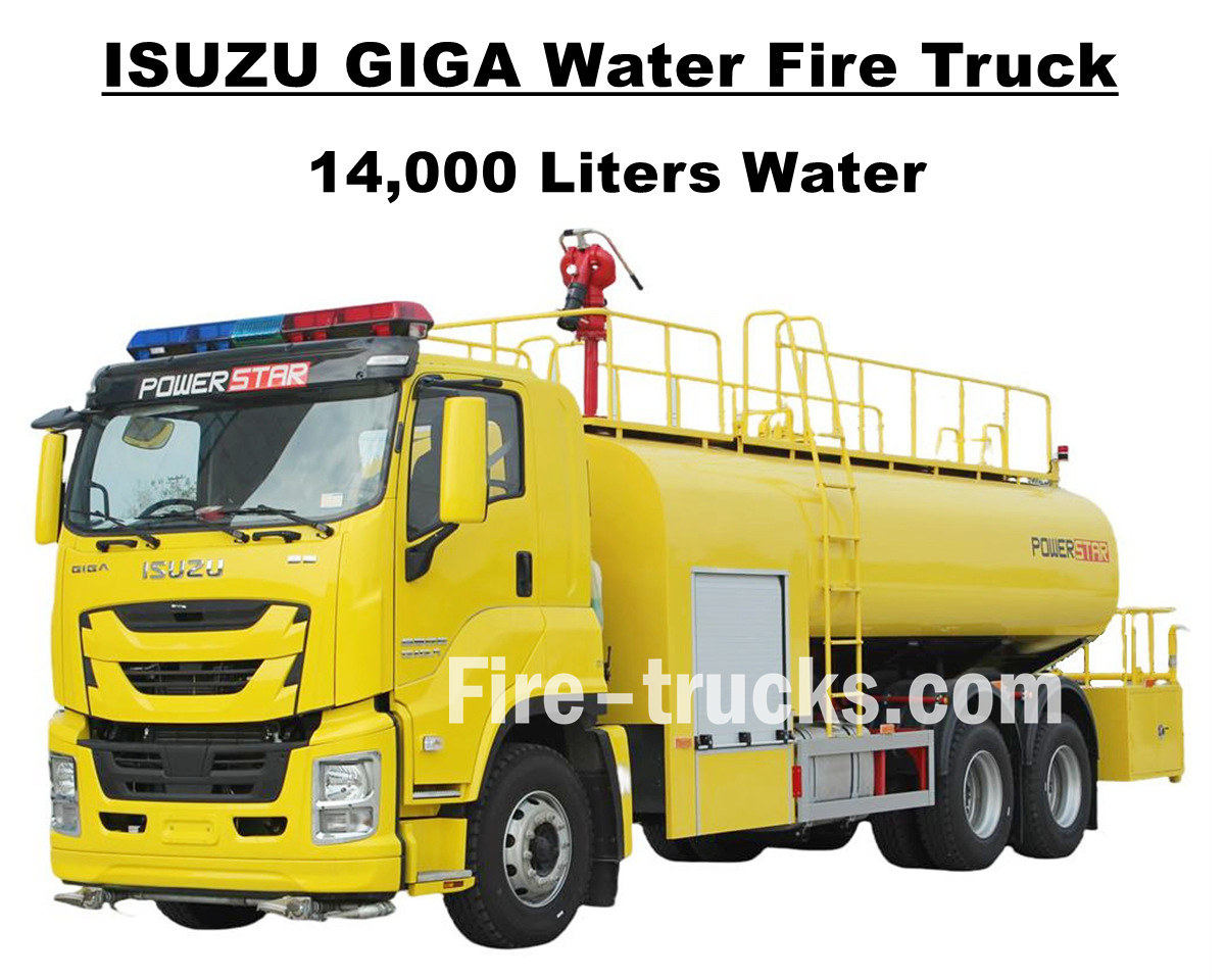
South American customer Mr Joseph from Hondura, who purchased 1 unit Isuzu GIGA VC66 14000L 3700gallons water fire fighting truck from POWERSTAR TRUCKS, which designed based on Japanese ISUZU GIGA 6x4 heavy duty truck chassis, equipped 6UZ1-TCG60 model diesel engine with horse power 280kw / 380HP, which is a 6-cylinder, 4-stroke, water-cooled, turbocharged and intercooled engine, efficiently displacement 9839ml, matched working with international standard FAST 12 shift manual transmission gearbox, 12 shift forward and 2 shift backward, efficiently reduce the fuel consumption, totally installed 13 units steel tires with model 12R22.5 model, including one spare tire, very suitable for multiple kinds of road condition and suitable for mountain climbing. Wheelbase can be multiple optional with 4600+1370mm, suitable and convenient designed service for fire extinguishing project for multiple area. Isuzu GIGA 3700 gallons water tanker fire engine fully rely on Japanese technology ISUZU truck chassis, original GIGA VC66 cabinet equipped A/C with heating and cooling function for comfortable driving. And truck mounted with full stainless steel SS304 material water tanker body, with efficiently volume 14000Liters, equal to 3700gallons, equipped with one Chinese brand CB10/60 fire pump and PS8/50 fire monitor on the top of tanker body, full sets fire fighting rescue equipment, and customized lemon yellow painting for whole truck, all make truck an ideal vehicle for fire extinguishing project in Honduras street and community. Also truck matched with full sets English version catalogue for service, including User's Manual for operation guidance, Truck Manual for GIGA truck usage, Spare Parts Manual for maintenance. Isuzu GIGA 14,000L Water Pumper Fire Fighting truck POWERSTAR factory is professional manufacturer in truck area,guarantee all products Brand-New and High-Quality. »Ⅰ. Isuzu Water Fire Truck Advantages : ★ 280KW / 380HP powerful 6WG1 diesel engine, 100,000 Km without prblem. ★ ISUZU VC66 newly GIGA cabin, Europen design ★ Mounted CB10/60 fire pump, 60L/s flow rate, super reliable ★ Top mounted PS8/50 water fire cannon, durable service ★ Integrated control system, with panel at side ★ Customized lemon yellow painting, shining and beautiful CB10/60 fire pump Model: CB10/60Pressure: 1.0MpaMax. Working Pressure: 1.232MpaFlow Rate: 60L/s at 1.0Mpa, speed 3286±50r/min, power 102kW, suction depth 3m42L/s at 1.3Mpa, speed 3519±50r/min, power 106kW, suction depth 3m30L/s at 1.0Mpa, speed 3120±50r/min, power 73kW, suction depth 7mSpeed Ratio: 1:1.44 PS8/50 Fire Monitor Model: PS8/50 Pressure: 0.8Mpa Working Range: Water ≥ 65m Vertical Rotation: ...
Details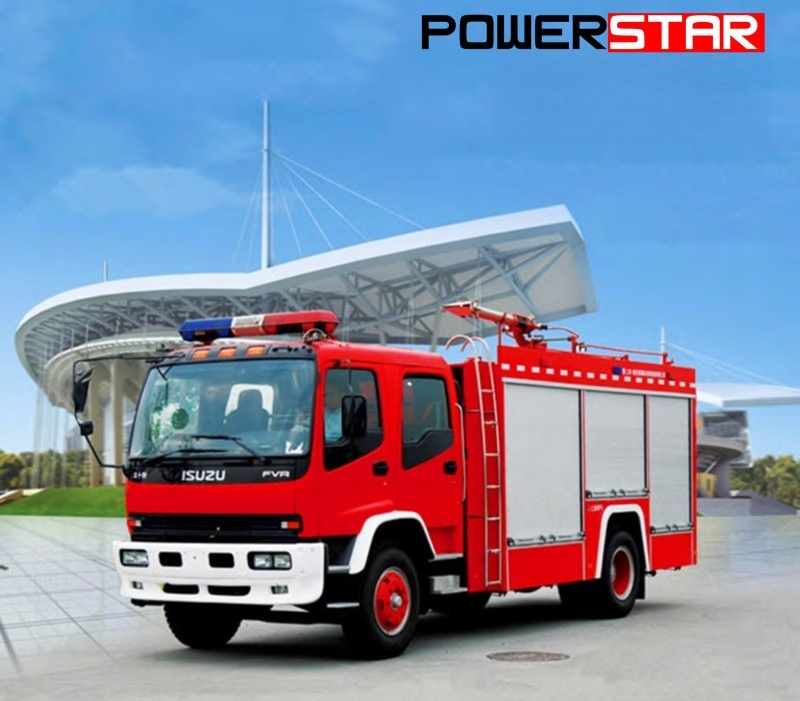
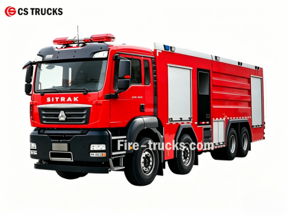
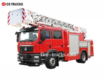
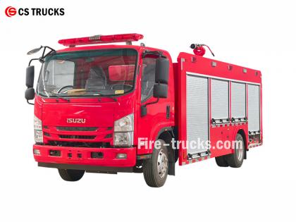
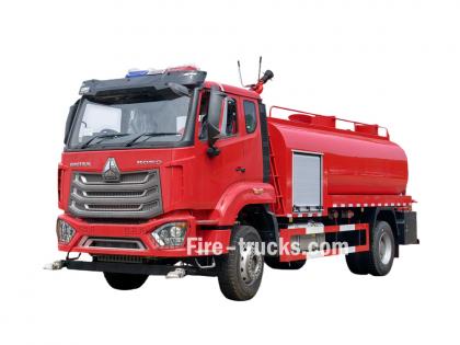
Powerstar Trucks Manufactures Custom Emergency Response Vehicles and Fire Trucks For several years, Powerstar trucks Emergency Response has established its legacy as the leading full-line manufacturer of custom fire apparatus with an expertise in foam water fire trucks and rescue fire vehicle. Building on the legacies that firefighters trust, Powerstar trucks delivers flexible, strategic, specialized solutions to meet each unique fire department need, putting first responders first. 120 units Rescue fire truck for delivery 65 units Rescue Fire Truck export to Uganda Police Water Fire trucks Foam fire fighting vehicle Fire trucks are mainly classified into four categories according to their function: fire-fighting trucks, aerial ladder trucks, special-purpose fire trucks, and logistical support fire trucks. 01, Fire-fighting trucks are the main force for directly extinguishing fires, including: * **Water Tank Fire Trucks:** Equipped with their own water tank and pump, suitable for extinguishing general fires. * **Foam Fire Trucks:** Specifically designed for extinguishing fires involving flammable liquids such as oil. * **Dry Powder Fire Trucks:** Suitable for extinguishing gas and electrical fires. * **Carbon Dioxide Fire Trucks:** Used to protect valuable equipment and precision instruments. * **Foam-Dry Powder Combined Use Trucks:** Can use both extinguishing agents simultaneously, with a wide range of applications. 02, Aerial Ladder Fire Trucks are used for rescue and firefighting in high-rise buildings, mainly including: * **Ladder Fire Trucks:** Equipped with a telescopic ladder, capable of rescuing people and extinguishing fires at heights. * **Aerial Spray Fire Trucks:** Use a remotely controlled boom to spray extinguishing agents over long distances. * **Aerial Platform Fire Trucks:** Provide a hydraulic lifting platform for rescue and firefighting. Fire truck application 03, Specialized fire trucks are responsible for specific tasks, such as: * **Rescue and Disaster Relief Fire Trucks:** Equipped with demolition tools and lifting equipment, used for accident rescue. * **Lighting Fire Trucks:** Provide high-intensity lighting for nighttime rescue operations. * **Smoke Extraction Fire Trucks:** Used for smoke extraction operations in underground fires. 04, **Logistical Support Fire Trucks:** Primarily provide logistical support to the fire scene, such as: * **Water Supply Fire Trucks:** Provide a continuous water supply to fire trucks at the front lines. **Equipment Fire Trucks:** Transport and replenish various firefighting equipment. Powerstar trucks fire truck factory strong technology
Details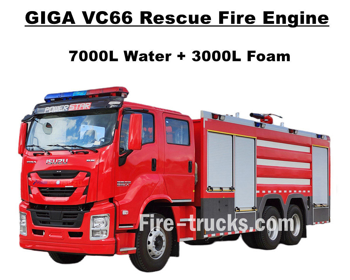
Philippines Manila customers purchased Isuzu GIGA VC66 heavy duty fire fighting truck from POWERSTAR TRUCKS, which equipped with Japanese ISUZU diesel engine 6WG1-TCG61 with horse power 338kw / 460HP, which is a 6-cylinder, 4-stroke, water-cooled, turbocharged and intercooled engine, designed displacement of 15681cc standard, matched working with international standard FAST 12 shift manual transmission gearbox, 12 shift move forward and 2 shift move back, very lower fuel consumption, totally installed 13 units tubeless tires with model 315/80R22.5 model, including one spare tire, very suitable for multiple kinds of road condition. and service for fire extinguishing project for multiple area. Fully rely on original ISUZU GIGA VC66 truck chassis, modify GIGA double-row cab with front 2+1 normal seats and rear 4 SCBA seats, in cabin equipped A/C with heating and cooling function for comfortable driving. And truck mounted with full stainless steel SS304 material tanker body, equipped Top one Chinese brand XIONGZHEN CB10/60 fire pump on rear pump room, matched working with WESTER PL8/48 fire monitor on the top of tanker body, full sets fire fighting rescue equipment, all make truck an ideal vehicle for fire extinguishing project in Manila street and community. Also truck matched with full sets English version catalogue for service, including User's Manual for operation guidance, Truck Manual for GIGA truck usage, Spare Parts Manual for maintenance. Isuzu 7,000L Water 3,000L Foam Fire Fighting truck POWERSTAR factory is professional manufacturer in truck area,guarantee all products Brand-New and High-Quality. »Ⅰ. Isuzu 6WG1 Fire Truck Main Features : ★ 338KW / 460HP powerful 6WG1 diesel engine, 100,000 Km without prblem. ★ ISUZU VC66 newly GIGA cabin, Europen design ★ Double row cabin, with rear 4 SCBA seats ★ Mounted CB10/60-XZ fire pump, 60L/s flow rate, super reliable ★ Top mounted PL8/48 foam fire cannon, durable service ★ Integrated control system, with panel at rear CB10/60-XZ fire pump Model: CB10/60-XZPressure: 1.0MpaMax. Working Pressure: 1.232MpaFlow Rate: 60L/s at 1.0Mpa, speed 3286±50r/min, power 102kW, suction depth 3m42L/s at 1.3Mpa, speed 3519±50r/min, power 106kW, suction depth 3m30L/s at 1.0Mpa, speed 3120±50r/min, power 73kW, suction depth 7mSpeed Ratio: 1:1.44 PL8/48 Fire Monitor Model: PL8/48 Pressure: 0.8Mpa Working Range: Foam ≥ 70m and Water ≥ 60m Vertical Rotation: -45° ~ +70° Horizontal Rotation: 0° ~ 360° Flow Rate: 48L/s » Ⅱ. Isuzu Fire Rescue Truck technical drawing: ISUZU GIGA VC66 fire engine mounted wi...
Details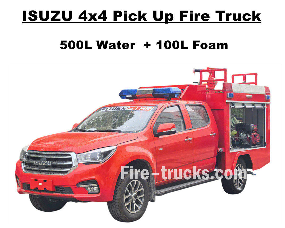
Factory sale ISUZU 4x4 offroad pick up fire truck use ISUZU TAGA all wheel drive chassis, integrates an excellent power system to challenge all kinds of difficult roads. Isuzu pickup fire rescue truck is equipped with full stainless steel SS304 material tanker assembly, including 500 liters water tank and 100 liters foam tank, and a professional independent fire pump JBQ4.5/9 to be mounted at rear pump room, with a long spray distance and optional control panel language. It also provides a variety of optional configurations to meet different needs, and top mounted with PS20 fire monitor for water jetting. This ISUZU Pickup 143HP fire pumper truck provides a solid guarantee for fire safety and demonstrates excellent performance and flexibility. The original double-row cab of the Isuzu fire fighting truck provides enough space and quality to load firefighting equipment and maintain good driving performance. The cab can accommodate 5 firefighters and is equipped with air conditioning to ensure that the driver can stay comfortable in any weather conditions. And all guarantee the ISUZU 600L foam fire engine an ideal fire rescue vehicle service for Albania market. And below User Manual are equipped for safety operation and working. »Ⅰ. Isuzu Pick Up Fire Truck Main Features : ★ 105KW / 143HP powerful 4KH1 engine, 100,000 Km without prblem. ★ ISUZU TAGA newly pickup cabin, Europen design ★ Original double cabin, suitable for 5 firefighters ★ Independent JBQ4.5/9 fire pump, super reliable ★ Top mounted PS8/20 fire cannon, durable service » Ⅱ. Pick up fire tender overview: ISUZU 4x4 offroad AWD Water Foam Fire Fighting Truck is an all terrain fire rescue trucks, which service for multiple aera, including community, forest, factory, etc. Due to it is offroad ability and narrow appearance, this Isuzu Pickup fire engine can succeed have multiple mission completed. And to make our fire trucks more suitable, below are options for different clients. -----Tanker material: Carbon steel, stainless steel, aluminum alloy, PP material -----Fire Pump: Based on tanker body and jetting distance, optional American Darley brand -----Optional: Pipeline, hose reel, aluminium ladder, Joint model (Chinese, European, American type) » Ⅲ. Attractive Appearance: ISUZU 4x4 AWD pick up fire truck is powerful and responsive, can quickly reach the fire scene, and can easily pass through complex terrain. The top fire cannon has a long range and a large flow rate, and the longer 50m fire fighting hose reel with gun can accurately strike the fire source and efficiently cover and isolate. And pickup fire pumper vehicles equipped with full set rescue tools. For different fire scenes, such as buildings, forests, oil tanks and hazardous chemical leaks, there are adaptive tactics that can be used for quick battles or precise attacks. And...
Details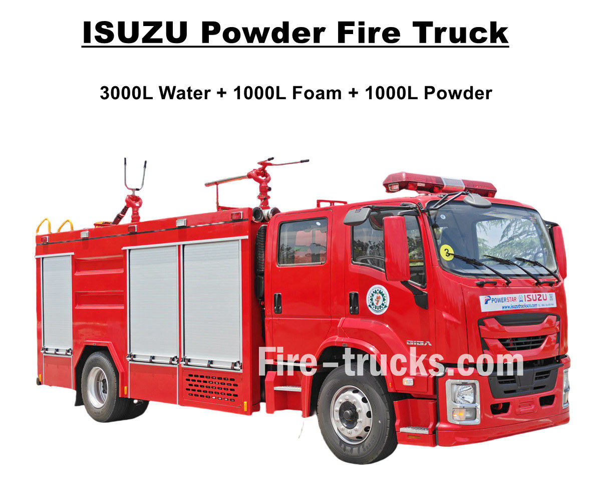
Newly designed and manufactured ISUZU GIGA 4X water foam dry powder fire fighting truck is a high performance ISUZU fire engine that export to Nigeria Lagos, which equipped with 4HK1-TCG60 diesel engine with 150KW/205HP and emission 5193cc, matched working with MLD 6 shift manual transmission gearbox, 6 forward and 1 reverse, efficiently power output and lower fuel consumption, also ensure faster response and stable driving. Isuzu 5000L fire engine equipped with totally 5000L tanker body kit, including 3000L water tanker, 1000L foam tanker and 1000L dry powder tanker, all tanker use stainless steel SS304 material, square shape design with baffle inside, top matched with DN500 manhole cover and lock for safety. Isuzu powder fire pumper trucks are equipped with CB10/40 fire pump, with efficiently flow rate 40L/s, matched working with PL8/32 water foam fire monitor with efficiently mixed water foam flow rate 32L/s, working with multiple fire rescue equipment to make the ISUZU giga 4X fire fighting vehicle an ideal vehicle for fire extinguishing and people rescue, and efficiently working in Nigeria Lagos country. Also truck matched with Dry Powder Tanker with model R25-006 series, designed pressure 1.55Mpa and designed volume 1000liters, also equipped with efficiently nitrogen bottles for usage. And to guarantee ISUZU fire trucks operation and performance more efficience, below attached manual are for equipment for Nigeria customer guidance. ♦ ISUZU GIGA Dry Powder Fire Fighting Truck ♦ POWERSTAR ISUZU Dry Powder Fire Truck Manual export Nigeria ISUZU fire fighting trucks control panel ISUZU fire rescue truck detailed component »Ⅰ. Isuzu Fire Truck Main Features : ★ 205 Hp powerful 4HK1 engine, 100,000 Km without prblem. ★ ISUZU GIGA new model 4X cabin, Europen design ★ ISUZU technology axle, extremely suitable for AFRICA. ★ China famous CB10/40 pump, super reliable ★ Top designed PL8/32 fire cannon, durable ★ Dry powder assembly, matched Nitrogen bottles » Ⅱ.ISUZU Fire Tender manufacturer: ISUZU GIGA Water Foam Dry Powder Fire Fighting Truck is a fully functional medium-sized main battle fire truck, integrating strong mobility, ample extinguishing agent reserves, and diverse combat capabilities. In terms of power, it features a Weichai engine paired with a Sinotruk transmission, providing strong power and efficient transmission. -----Tanker material: Carbon steel, stainless steel, aluminum alloy, PP material -----Fire Pump: Based on tanker body and jetting distance, optional American Darley brand -----Optional: Pipeline, hose reel, aluminium ladder, Joint model (Chinese, European, American type) Isuzu rescue fire trucks for production ISUZU 205HP fire fighting truck for production Isuzu GIGA 4X powder fire fighting truck » Ⅲ. Isuzu Fire Pumper Advanced Features: Isuzu combin...
Details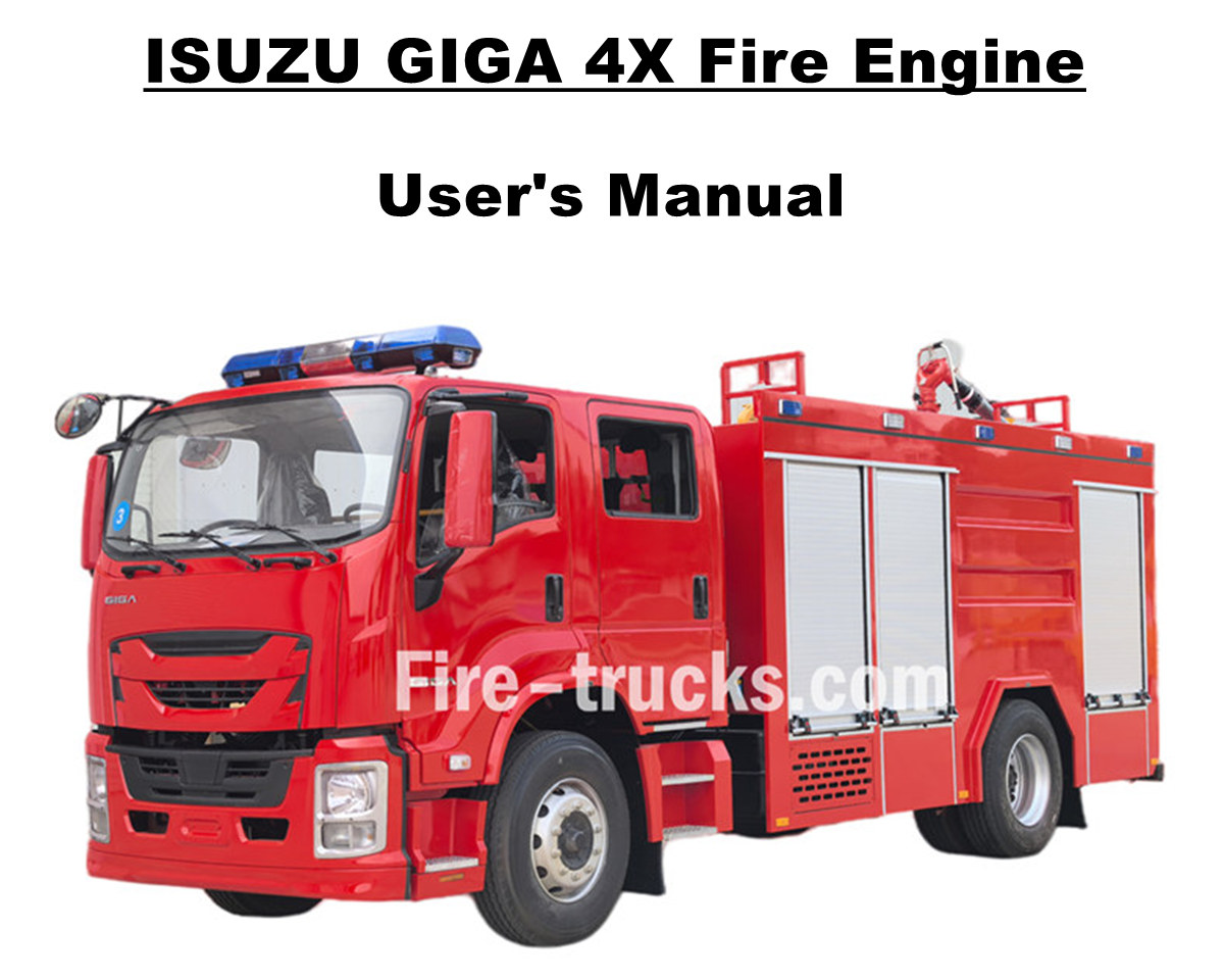
Moldova customers purchased 6 units Isuzu GIGA 4X airport fire rescue truck from POWERSTAR TRUCKS, and service for fire extinguishing project for multiple area. Fully rely on original ISUZU GIGA 4X truck chassis, modify GIGA 4X double-row cab with front 2+1 normal seats and rear 4 SCBA seats, in cabin equipped A/C with heating and cooling function for comfortable driving. Equipped with Japanese ISUZU diesel engine 4HK1-TCG60 with horse power 151kw / 205HP, which is a four-cylinder, four-stroke, water-cooled, turbocharged and intercooled engine, designed displacement of 5193cc standard, matched working with ISUZU MLD 6 shift manual transmission gearbox, 6 shift move forward and 1 shift move back, very lower fuel consumption, totally installed 7 units tubeless tires with model 295/80R22.5 model, very suitable for multiple kinds of road condition. Isuzu 5,000L Water 1,000L Foam Fire truck POWERSTAR factory is professional manufacturer in truck area,guarantee all products Brand-New and High-Quality. » Ⅰ. Firefighting Applications: ISUZU GIGA 4X newly designed 205HP fire fighting truck mounted with full set fire fighting equipment and people rescue tools, with efficiently water and foam jetting distance and flow rate, and suitable for multiple fire extinguishing work in city, factory, community, etc. Detailed advanced features as below: 1. ISUZU GIGA 4X Truck: Japanese ISUZU 4HK1-TCG60 model with 151KW / 205HP diesel engine 2. SS304 Material Tanker: Customized 5000L water tanker and 1000L foam tanker, all based on stainless steel SS304 3. CB10/40 Fire Pump: Rear mounted, with independent room, available pump in and pump out function CB10/40 fire pump Model: CB10/40Pressure: 1.0MpaMax. Working Pressure: 1.38MpaFlow Rate: 40L/s at 1.0Mpa, speed 3330±50r/min, power 60kW, suction depth 3m28L/s at 1.3Mpa, speed 3540±50r/min, power 59kW, suction depth 3m20L/s at 1.0Mpa, speed 3335±50r/min, power 42kW, suction depth 7mSpeed Ratio: 1:1.542 4. PL8/36 Fire Monitor: Top mounted, manual operaiton model with available jetting distance over 55m, efficiently and durable PL8/36 Fire Monitor Model: PL8/36 Pressure: 0.8Mpa Working Range: Foam ≥ 60m and Water ≥ 48m Vertical Rotation: -45° ~ +70° Horizontal Rotation: 0° ~ 360° Flow Rate: 36L/s 5. Integrated Control Device: ISUZU fire fighting trucks equipped with integrated control device at rear pump room, convenient and smart. » Ⅱ. Fire Engine Advanced Features: ISUZU GIGA 4X heavy duty rescue fire engine are an ideal fire fighting truck for fire extinguishing and people rescue. Which ha...
Details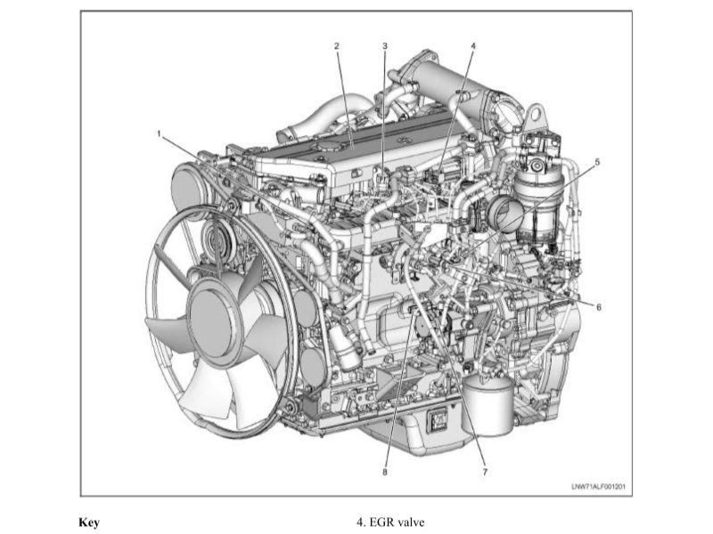
The Isuzu Fire Truck 4HK1-TC Engine Maintenance Manual, also called Engine repair manual of Isuzu fire tender or Engineer book of Isuzu fire fighting vehicle. The Isuzu Fire Truck 4HK1-TC engine is a high-performance diesel engine widely used in fire trucks, known for its reliability, durability and high efficiency. In order to ensure the long-term stable operation of the engine, regular maintenance and repair are essential. This article will briefly introduce the main contents of the Isuzu Fire Truck 4HK1-TC Engine Maintenance Manual to help maintenance personnel better understand and operate. 1. Engine Overview The 4HK1-TC engine is a 4-cylinder inline turbocharged diesel engine with a displacement of 5.2 liters and a maximum power of 190 horsepower. The engine uses an advanced common rail fuel injection system and an electronic control unit (ECU) to achieve higher fuel efficiency and lower emissions. 2. Daily Maintenance Daily maintenance is the basis for ensuring the normal operation of the engine. The maintenance manual lists in detail the items for daily inspection, including oil and coolant level inspection, air filter cleaning or replacement, fuel filter replacement, etc. In addition, the manual also provides recommendations for regular replacement of engine oil and oil filter, usually every 5,000 kilometers or every 6 months. 3. Fault Diagnosis The maintenance manual contains a detailed fault diagnosis process to help maintenance personnel quickly locate and solve problems. The manual lists common fault codes and their meanings, and provides corresponding solutions. For example, if the engine is underpowered, the manual will guide maintenance personnel to check the fuel system, turbocharger and exhaust system, etc. 4. Overhaul and Parts Replacement For engines that need overhaul or replacement of parts, the maintenance manual provides detailed steps and precautions. For example, when replacing key components such as piston rings, valve guides and bearings, the manual will detail the steps for removal and installation, as well as the required tools and torque specifications. 5. Safety Precautions The maintenance manual places special emphasis on the importance of safe operation. Before performing any maintenance operations, you must ensure that the engine has been completely cooled and the power supply is disconnected. In addition, the manual also provides recommendations for the use of personal protective equipment, such as gloves, goggles and protective clothing. Section 1A Engine control system Table of Contents Page Engine control system.. 1A-4 Precautions 1A-4 Function and working principle. 1A-5 Parts configuration diagram.. 1A-21 Circuit diagram.. 1A-25 How to diagnose the fault 1A-42 Fault diagnosis operation procedures through fault diagnostic meter 1A-48 Functional check overview.. 1A-50 Inquiry. 1A-51 Engine control system check. 1A-53 Fault diagnostic me...
Details
Please subscribe latest fire trucks news, and Warmly welcome to tell us what you think.

 IPv6 network supported

 English
 français
 Deutsch
 русский
 italiano
 español
 português
 Nederlands
 العربية
 日本語
日本語 한국의
한국의 Türkçe
 Melayu
 ไทย
ไทย Tiếng Việt
 Indonesia
  中文
中文 қазақ
қазақ Filipino
 မြန်မာ
 српски