Leave A Message
If you are interested in our products and want to know more details,please leave a message here,we will reply you as soon as we can.

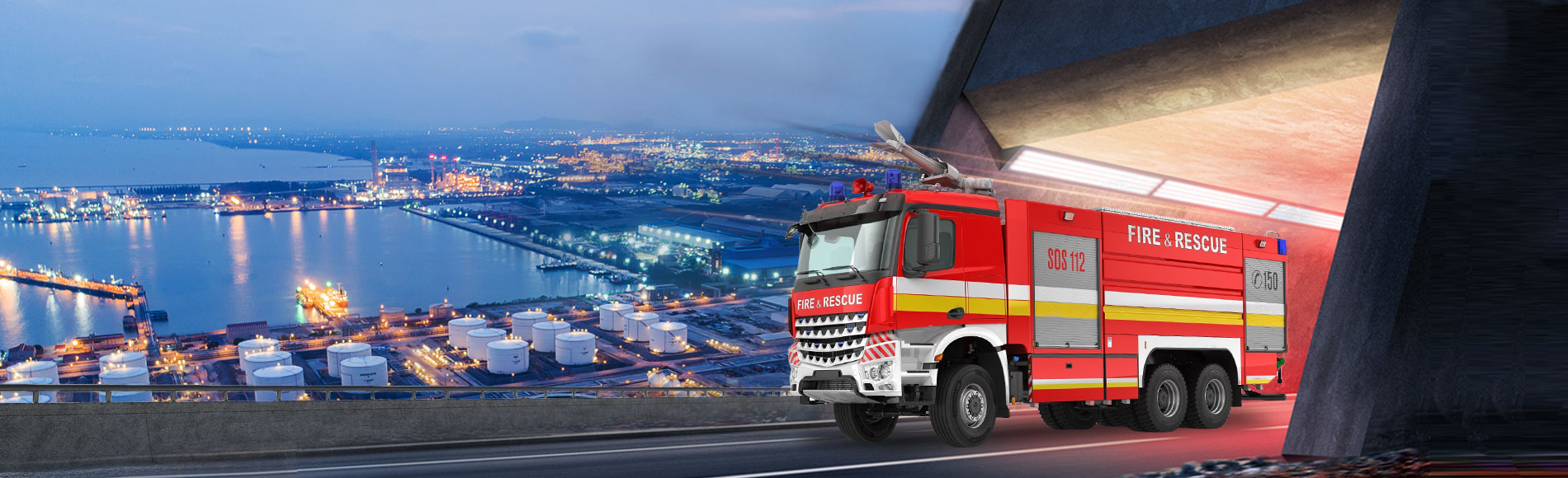
A fire pump is the heart of every fire truck's water delivery system. Whether responding to a structural fire, industrial emergency, airport incident, or wildland operation, the fire pump on a fire truck is responsible for delivering high-pressure water to hoses, fire monitors, and foam systems. Its centrifugal impeller design and PTO-driven system ensure stable pressure and high flow rates, directly increasing firefighting effectiveness by over 40%, while reducing response time by 3 times. It can be called the invisible guardian of firefighting operations and the technical cornerstone of modern emergency response.
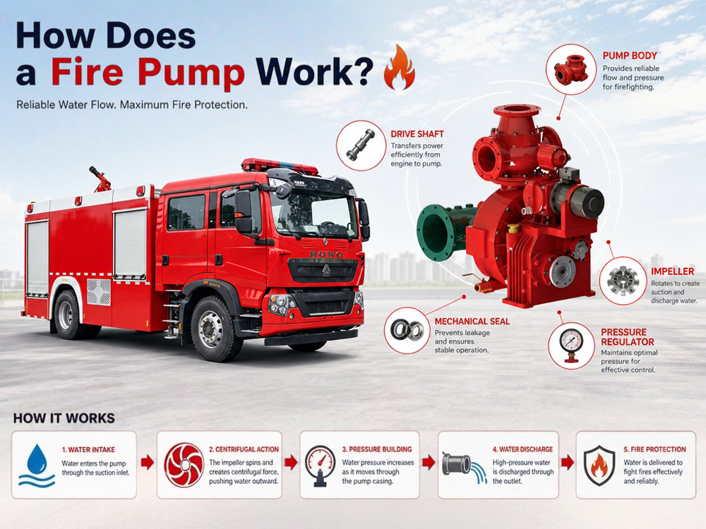
Learn how a fire pump works, including its working principle, major components, water flow process, pressure generation, and applications. Discover how fire truck pumps deliver reliable water supply for firefighting and how to choose the right pump for your fire apparatus. Let's learn about it today.
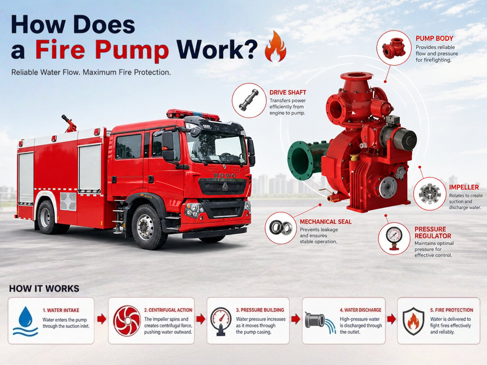
1. Power is transferred from the engine through the PTO
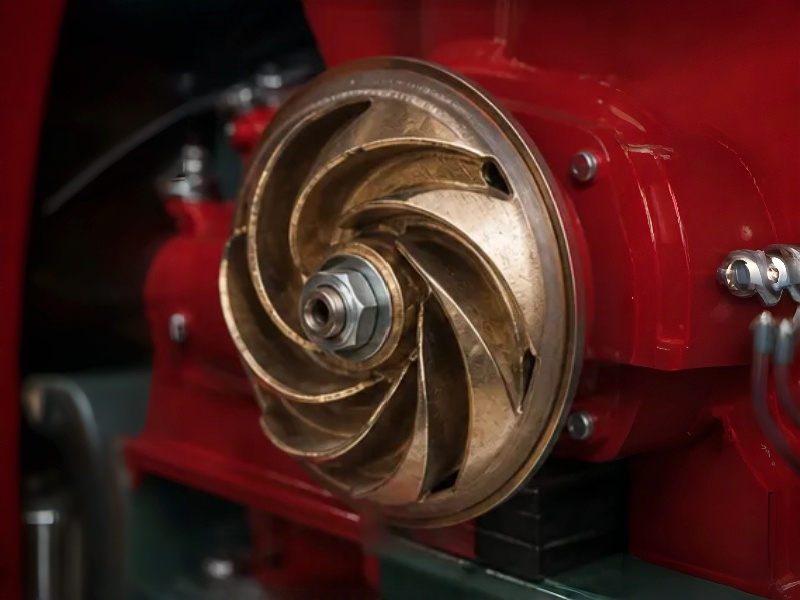
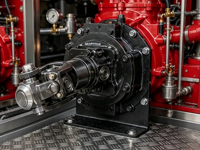
The truck engine drives the PTO, which connects to the pump shaft. When the operator engages the PTO, engine power is redirected to spin the pump impeller at high speed.
2. The impeller begins rotating
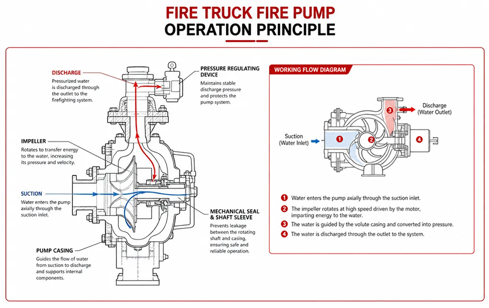
The impeller spins at 1,500–2,500 RPM, drawing water into the pump through the suction inlet. The spinning impeller blades create a low-pressure zone at the center, pulling water in from the onboard tank, hydrant, or natural water source.
3. Centrifugal force increases water pressure
As the impeller spins, it throws water outward by centrifugal force. The water's velocity increases as it moves from the center to the outer edge of the impeller. The pump casing then converts this velocity into pressure, forcing high-pressure water out through the discharge outlet.
4. High-pressure water exits the discharge outlet
Pressurized water (typically 0.8–1.2 MPa) exits through the discharge outlet and is delivered to fire hoses, fire monitors, or foam proportioning systems for firefighting operations.
The fire pump can draw water from three sources:
Onboard water tank: The primary water source for initial attack. Typical capacity: 2,000–12,000 liters. Provides immediate water supply upon arrival.
Fire hydrant: Connected through supply hoses. Provides continuous water supply for extended operations. Pressure from hydrant helps the pump maintain flow.
Natural water source (drafting): Lakes, rivers, ponds, or swimming pools. The pump uses a priming system to remove air from the suction hose before drafting. Maximum theoretical lift at sea level: approximately 10 meters (33 feet). Effective drafting depth: typically 7–8 meters.
Suction process:
Connect rigid suction hose to pump intake
Submerge strainer at least 2-3 feet below water surface
Engage primer to remove air from hose and pump
Vacuum builds, atmospheric pressure pushes water up
Water fills the pump, then the centrifugal pump pressurizes it
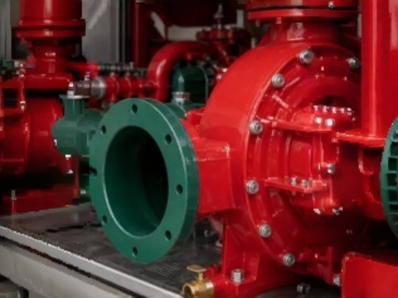
Suction inlet: Where water enters the pump. Typical size: DN100–DN150. Equipped with strainer to prevent debris from entering.
Discharge outlet: Where pressurized water exits. Typical size: DN65–DN80 (standard outlets). Equipped with valves to control flow to hoses or monitors. Multiple outlets allow simultaneous use.
Impeller: The rotating component that creates water flow. Converts mechanical energy into kinetic energy. Typically made of bronze (corrosion-resistant), stainless steel (durable, long-lasting), or cast iron (cost-effective for standard applications).
Pump casing: The housing that directs water flow. Designed to convert velocity into pressure. Common designs: volute casing (spiral shape for smooth flow) and diffuser casing (for higher efficiency).
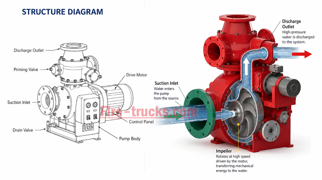 Primer system: Removes air from the pump and suction hose before drafting. Types include:
Vacuum primer: Rotary vane or piston design. Fast and efficient. Most common in modern fire trucks.
Exhaust primer: Uses engine exhaust to create vacuum. Simple but less effective.
Electric primer: Motor-driven. Can prime without pump rotation. Protects mechanical seal from dry running damage.
Pressure relief valve: Prevents over-pressurization. Opens when pressure exceeds set limit. Protects hoses, pump, and firefighters.
Pressure governor: Automatically maintains set pressure. Adjusts engine RPM to compensate for flow changes. Reduces operator workload. Available in pressure mode (maintains preset pressure) and RPM mode (maintains preset engine speed).
PTO (Power Take-Off): The connection between engine and pump. Transfers engine power to drive the pump. Fire trucks typically use sandwich PTO (mounted between engine and transmission) for full power output.
| Pump Type | Advantages | Typical Applications |
|---|---|---|
| Single-stage centrifugal pump | High flow, simple design, cost-effective | Municipal fire trucks |
| Two-stage fire pump | Higher pressure, switchable modes | High-rise firefighting, long hose lays |
| Midship fire pump | Better balance, stable operation | Standard fire apparatus |
| Rear-mounted fire pump | Easier maintenance, better cooling | Airport and industrial trucks |
| Comparison Item | Fire Pump | Standard Water Pump |
|---|---|---|
| Working pressure | High (0.8–2.5 MPa) | Lower (0.2–0.6 MPa) |
| Flow rate | High (1,200–6,000 L/min) | Moderate (500–2,000 L/min) |
| Continuous operation | Yes (designed for extended use) | Depends on model |
| PTO driven | Yes | Usually not |
| Firefighting standard compliance | Yes (NFPA, EN, GB certified) | No |
| Application areas | Firefighting and rescue | Industrial, agricultural, domestic water supply |
| Application | Recommended Pump | Reason |
|---|---|---|
| Municipal firefighting | Single-stage (1,200–3,000 L/min) | Cost-effective, sufficient for most fires |
| High-rise buildings | Two-stage (2,000–4,000 L/min) | Higher pressure for vertical lift |
| Petrochemical plants | Two-stage (3,000–6,000 L/min) | High flow, pressure for industrial fires |
| Airport crash rescue | Rear-mounted (4,000–6,000 L/min) | High flow, easier maintenance |
| Wildland firefighting | Single-stage (1,000–2,000 L/min) | Lightweight, portable |
The fire pump builds pressure through centrifugal force. When the impeller rotates, it draws water into the center and throws it outward at high speed. The pump casing converts this high-velocity water into pressure by slowing it down.
Factors affecting pressure:
Impeller speed: Faster rotation = higher pressure. Impeller speed is directly proportional to engine RPM.
Engine RPM: Higher engine speed = faster impeller = higher pressure. Operators control pressure by adjusting engine throttle or using the pressure governor.
Pump design: Two-stage pumps can achieve higher pressure than single-stage pumps by using two impellers in series.
Pipe diameter: Smaller diameter = higher pressure but lower flow. Larger diameter = lower pressure but higher flow. The operator must balance pressure and flow based on the firefighting task.
Water source: Adequate water supply is essential for maintaining pressure. Insufficient supply causes pressure to drop.
1. Pump won't prime
Possible causes: Air leak in suction hose, clogged strainer, primer not working.
Solutions: Check and tighten all suction hose connections; clean the strainer; inspect the primer system (vacuum pump or electric primer) and repair if needed.
2. Low water pressure
Possible causes: Clogged strainer, insufficient engine RPM, worn impeller, air in system.
Solutions: Clean the strainer; increase engine speed; inspect impeller for wear and replace if needed; check for air leaks and prime again.
3. Cavitation
Formation: Cavitation occurs when the pump does not receive enough water. The impeller spins in a mixture of water and vapor bubbles. When these bubbles collapse, they create shock waves that damage the impeller and cause severe pressure fluctuation.
How to avoid: Never run the pump faster than the water supply can deliver; monitor intake pressure; reduce pump speed if vacuum is too high; ensure strainer is not clogged.
4. Water leakage
Check items: Check all seals and gaskets; inspect for cracks in the pump casing; ensure drain valves are closed; replace worn seals immediately.
5. Overheating
Causes: Pump running dry, insufficient cooling, prolonged operation without water flow.
Maintenance tips: Never run the pump without water; ensure cooling lines are clear; allow the pump to cool between operations; check the thermal relief valve regularly.
» VIII. Real case study: Municipal fire department pump upgrade
Background:
A municipal fire department with a fleet of aging fire trucks needed to upgrade the pump systems on three frontline engines. The existing pumps struggled to maintain pressure during high-rise firefighting operations and frequently required repairs.
Challenge:
Pressure unstable at heights above 50 meters
Slow drafting from natural water sources (priming time >45 seconds)
Low flow rate at high pressure
Frequent seal failures and impeller wear
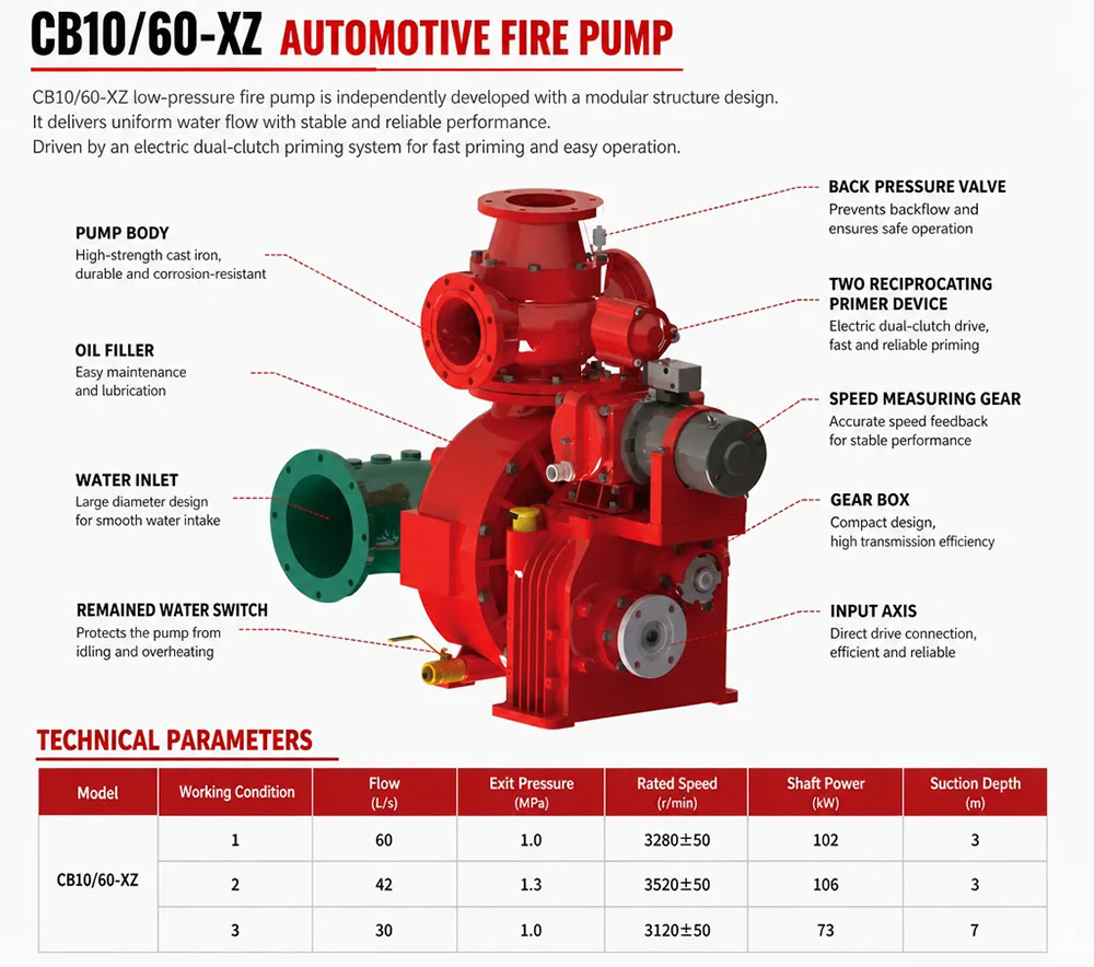
Solution:
CB10/60 fire pump (60 L/s @ 1.0 MPa)
Electric vacuum primer (improves priming speed)
Automatic pressure governor (maintains stable pressure)
Upgraded pump seals and bearings
New suction hoses with larger strainers
Results:
1. Determine required flow rate
| Application | Recommended Flow Rate |
|---|---|
| Municipal firefighting | 30–60 L/s |
| Industrial parks | 60–100 L/s |
| Airport crash rescue | 100+ L/s |
| Wildland firefighting | 20–40 L/s |
| High-rise buildings | 40–80 L/s |
2. Determine required pressure
| Application | Recommended Pressure |
|---|---|
| Municipal firefighting | 0.8–1.0 MPa |
| Industrial parks | 1.0–1.2 MPa |
| Petrochemical plants | 1.2–1.4 MPa |
| Airport crash rescue | 1.0–1.2 MPa |
| High-rise buildings | 1.5–2.5 MPa |
3. Consider water source
Hydrant supply: Single-stage pump is sufficient. No priming required.
Onboard tank: Single-stage or two-stage. Priming required for drafting.
Natural water (drafting): Requires vacuum primer. Two-stage for high lift.
4. Fire truck size and configuration
| Chassis | Recommended Pump |
|---|---|
| 4×2 | Single-stage, 1,200–2,000 L/min |
| 4×4 | Single-stage, 2,000–3,000 L/min |
| 6×4 | Two-stage, 3,000–4,500 L/min |
| 8×4 | Two-stage, 4,000–6,000 L/min |
Q: What is a fire pump?
A: A fire pump is a centrifugal pump driven by the truck engine through a PTO system. It draws water from onboard tanks, hydrants, or natural water sources, increases water pressure by spinning an impeller, and delivers high-pressure water to hoses or fire monitors for firefighting operations.
Q: How does a fire pump increase water pressure?
A: The impeller spins at high speed (1,500–2,500 RPM), drawing water into the center and throwing it outward by centrifugal force. The pump casing converts this high-velocity water into pressure by slowing it down. Higher impeller speed = higher pressure.
Q: Is a fire pump the same as a standard water pump?
A: No. Fire pumps are designed for higher pressure (0.8–2.5 MPa), higher flow rates (1,200–6,000 L/min), and continuous emergency operation. Standard water pumps operate at lower pressure and are not designed for firefighting or PTO-driven systems.
Q: What powers a fire truck pump?
A: The fire truck engine powers the fire pump through a Power Take-Off (PTO) system. When the operator engages the PTO, engine power is redirected to spin the pump impeller. No separate engine is required.
Q: Why does a fire pump need a primer?
A: A primer removes air from the pump and suction hose before drafting from a lake, river, or pond. Centrifugal pumps cannot move water if there is air in the system. The primer creates a vacuum, allowing atmospheric pressure to push water into the pump.
Q: What is the difference between a single-stage and a two-stage fire pump?
A: A single-stage pump has one impeller and provides high flow at moderate pressure. A two-stage pump has two impellers in series and can provide higher pressure. Two-stage pumps can switch between volume mode (high flow) and pressure mode (high pressure).
Q: Can a fire pump draw water from a river?
A: Yes. A fire pump can draw water from rivers, lakes, ponds, and swimming pools through a process called drafting. The primer removes air from the suction hose and pump, creating a vacuum. Atmospheric pressure pushes water up into the pump. Maximum practical lift: approximately 7–8 meters.
Q: What causes fire pump cavitation?
A: Cavitation occurs when the pump does not receive enough water. The impeller spins in a mixture of water and vapor bubbles. When these bubbles collapse, they create shock waves that damage the impeller. Cavitation is caused by running the pump faster than the water supply can deliver, clogged strainers, or excessive suction lift.
Q: How often should a fire pump be serviced?
A: Daily checks (noise, vibration, leaks) weekly tests (primer, pressure governor), monthly inspections (impeller, bearings, relief valve), yearly full flow tests and hydrostatic pressure testing. Regular maintenance prevents unexpected failures during emergencies.
Q: How do I choose the right fire pump for my fire truck?
A: Consider required flow rate (based on fire risks), pressure requirements (based on building heights), water source (hydrant, tank, or natural), fire truck chassis (4×2, 4×4, 6×4, 8×4), pump brand and reliability, and maintenance and service support. The pump must match the vehicle's engine power and PTO configuration.
Fire pumps use centrifugal force to increase water pressure. The impeller draws water in and throws it outward, converting velocity into pressure.
Most fire truck pumps are powered through a PTO system (Power Take-Off). Engine power is redirected to the pump, no separate engine is required.
Water can come from onboard tanks, hydrants, or open water sources. Drafting from natural sources requires a primer to remove air from the suction hose.
Priming systems remove air before drafting from natural water sources. Vacuum primers are most common, with electric primers offering protection for mechanical seals.
Pump performance depends on flow rate, pressure, impeller size, and engine power. Matching the pump to the firefighting task is critical.
Proper maintenance (daily, weekly, monthly, yearly) improves reliability and service life. Regular testing prevents unexpected failures during emergencies.
Understanding pump operation helps buyers choose the right specifications for their fire truck. The pump must match the chassis, PTO, and firefighting requirements.


You may be interested in the following information
A fire pump is the heart of every fire truck's water delivery system. Whether responding to a structural fire, industrial emergency, airport incident, or wildland operation, the fire pump on a fire truck is responsible for delivering high-pressure water to hoses, fire monitors, and foam systems. Its centrifugal impeller design and PTO-driven system ensure stable pressure and high flow rates, directly increasing firefighting effectiveness by over 40%, while reducing response time by 3 times. It can be called the invisible guardian of firefighting operations and the technical cornerstone of modern emergency response. Learn how a fire pump works, including its working principle, major components, water flow process, pressure generation, and applications. Discover how fire truck pumps deliver reliable water supply for firefighting and how to choose the right pump for your fire apparatus. Let's learn about it today. » I. First, we need to know the three key components of the fire pump system: 1.Impeller The rotating component that draws water in and throws it outward by centrifugal force. Typically made of bronze, stainless steel, or cast iron. 2.Pump casing The housing that contains the impeller and directs water flow. Designed to convert velocity into pressure. 3.Power Take-Off (PTO) The mechanical connection that transfers engine power from the truck's transmission to the fire pump. » II. After knowing the key components, the core working principle of the fire pump is as follows: 1. Power is transferred from the engine through the PTO The truck engine drives the PTO, which connects to the pump shaft. When the operator engages the PTO, engine power is redirected to spin the pump impeller at high speed. 2. The impeller begins rotating The impeller spins at 1,500–2,500 RPM, drawing water into the pump through the suction inlet. The spinning impeller blades create a low-pressure zone at the center, pulling water in from the onboard tank, hydrant, or natural water source. 3. Centrifugal force increases water pressure As the impeller spins, it throws water outward by centrifugal force. The water's velocity increases as it moves from the center to the outer edge of the impeller. The pump casing then converts this velocity into pressure, forcing high-pressure water out through the discharge outlet. 4. High-pressure water exits the discharge outlet Pressurized water (typically 0.8–1.2 MPa) exits through the discharge outlet and is delivered to fire hoses, fire monitors, or foam proportioning systems for firefighting operations. » III. Where does the fire pump get water? The fire pump can draw water from three sources: Onboard water tank: The primary water source for initial attack. Typical capacity: 2,000–12,000 liters. Provides immediate water supply upon arrival. Fire hydrant: Connected through supply hoses. Provides continuous water supply for extended operations. Pressure from hydrant helps the pum...
Details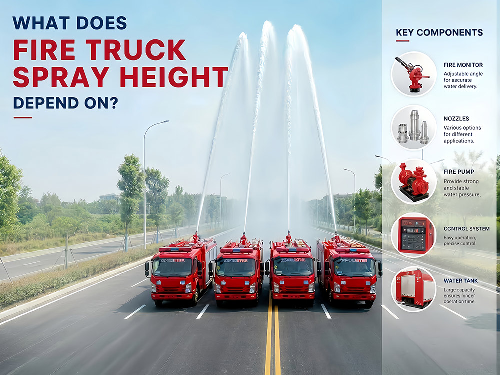
The fire truck pump and spray system is the core of firefighting operations. It acts as the "powerful arm" of the fire truck. By converting engine power into pressure (ranging from 0.8 to 1.4 MPa), it delivers extinguishing agents to heights of up to 85 meters — whether it is a high-rise building fire in a dense city center or a petrochemical storage tank fire in an industrial zone, the fire truck relies on this system to achieve effective fire suppression. What factors affect a fire truck's spray height, and how do pump pressure, flow rate, and fire monitor work together? These are the focus of many customers. Let's learn about it today. » I. Three Key Components That Determine Spray Height 1. Fire pump system: The heart of the fire truck. Centrifugal pump driven by PTO. Common pressure grades: 0.8 MPa, 1.0 MPa, 1.2 MPa, 1.4 MPa. Flow rates from 2,000 to 5,000+ L/min. 2.Fire monitor: The final component before the extinguishing agent leaves the truck. Available in water monitor, foam monitor, and dual-purpose monitor. PL-series (PL48) with flow rates up to 4,000 L/min and spray height up to 70+ meters. 3. Delivery system: Piping, hoses, and nozzles that carry the extinguishing agent from the pump to the monitor. Hose diameter, length, and nozzle type all affect final spray height. » II. Core Factors That Determine Spray Height 1.1. Pump Pressure Fire truck pump pressure is the force generated by the fire pump to push the extinguishing agent through hoses and discharge it from nozzles or monitors. It is the primary driver of both flow rate and spray distance. Higher pressure produces higher velocity at the monitor outlet, directly increasing spray height. The relationship is governed by the formula H ≈ P/(ρg), where each 0.1 MPa increase adds approximately 10 meters of theoretical height — but real-world losses reduce this. In practical firefighting operations, the following ranges apply: Pump Pressure Typical Spray Height 0.8 MPa 35–45 meters 1.0 MPa 45–55 meters 1.2 MPa 55–70 meters 1.4 MPa 70–85 meters 1.2. How the fire pump works: The pump is typically a centrifugal pump driven by the truck's engine through a power take-off (PTO). As the impeller spins, it draws the extinguishing agent in and throws it outward by centrifugal force, creating pressure that propels it through the discharge system. Rated Pressure vs. Operating Pressure: Term Definition Rated Pressure The maximum pressure the pump can sustain continuously under design conditions Operating Pressure The actual pressure used during firefighting, typically lower than rated pressure to allow margin 2. Flow Rate (L/min) Adequate flow is as important as pressure. High pressure with low flow cannot deliver enough extinguishing agent to suppress a fire. The pump system must maintain both pressure and flow simultaneously. Flow vs. spray height: 2,000 L/min → effective for municipal fires 3,000 L/min → suitable...
Details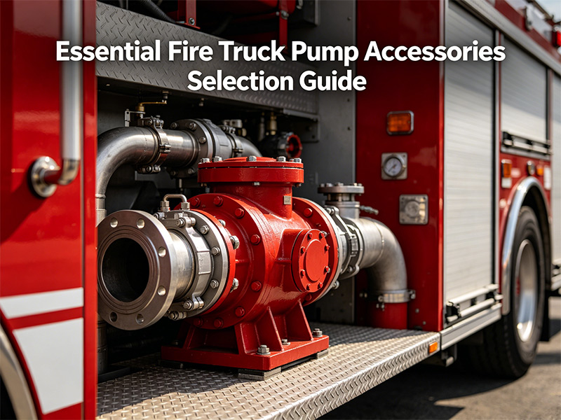
A fire truck pump system is only as reliable as its components. From drawing water from a source to discharging it at high pressure, every accessory plays a critical role. This guide covers fire truck five key accessory categories: primers, ball valves, globe valves, foam proportioners, and hydraulic control systems. Understanding these components helps firefighters maintain their equipment and choose the right accessories for specific applications. I. Primer Series (Vacuum Priming Devices) Primers are essential for drawing water from lakes, rivers, or other static sources when a hydrant is not available. They remove air from the pump and suction hose, allowing atmospheric pressure to push water into the pump. Product Overview Product Max Vacuum Voltage Power Suitable Pump Size 2-piston primer >85kPa 24V - Below 100 L/s Electric 2-piston primer >85kPa 24V 2.1KW Below 100 L/s 4-piston primer >85kPa 24V - Above 100 L/s Electric 4-piston primer >85kPa 24V 2.1KW Above 100 L/s Key Feature: Electric Primers Electric primers offer a significant advantage — they can prime the pump without the pump rotating. This protects the mechanical seal from dry running damage. When a standard primer requires the pump to spin, the electric version works independently, extending seal life. II. Ball Valve Series (Flow Control) Ball valves control water flow through hoses and discharge outlets. They are designed for quick on/off operation with a simple 90° turn. Stainless Steel Ball Valves Model Material Rated Pressure Thread Operation FQS65/2.5 Body & ball: 304 stainless steel; Seal: PTFE 2.5 MPa G2-1/2" Handwheel / Lever FQS80/2.5 Body & ball: 304 stainless steel; Seal: PTFE 2.5 MPa G3" Handwheel / Lever Aluminum Alloy Ball Valves (Lighter weight) Model Material Rated Pressure Thread Operation FQS65/2.5 Body: A356.2; Ball: 304; Seal: PTFE 2.5 MPa G2.5" Handwheel / Lever FQS80/1.6 Body: A356.2; Ball: 304; Seal: PTFE 1.6 MPa G3" Handwheel / Lever FQS65/2.5 Square Body: A356.2; Ball: 304; Seal: PTFE 2.5 MPa - Pneumatic / Lever Ⅲ. Globe Valve Series (Pressure & Flow Regulation) Unlike ball valves that are designed for on/off operation, globe valves allow precise control of flow rate and pressure. They are ideal for situations where gradual adjustment is needed. Model Material Rated Pressure Thread Operation DN65/2.5 Body: A356.2; Stem: H62; Seal: NBR 2.5 MPa G2.5" Handwheel DN80/2.5 Body: A356.2; Stem: H62; Seal: NBR 2.5 MPa G3" Handwheel When to Use a Globe Valve Use globe valves at discharge points where fine pressure control is required, such as when filling another vehicle's tank or supplying a hose line at a specific pressure. IV. Foam Proportioner Series (Foam Mixing Equipment) Foam proportioners mix foam concentrate with water at precise ratios. This is essential for fighting Class B (flammable liquid) fires where water alone is ineffective. Ma...
Details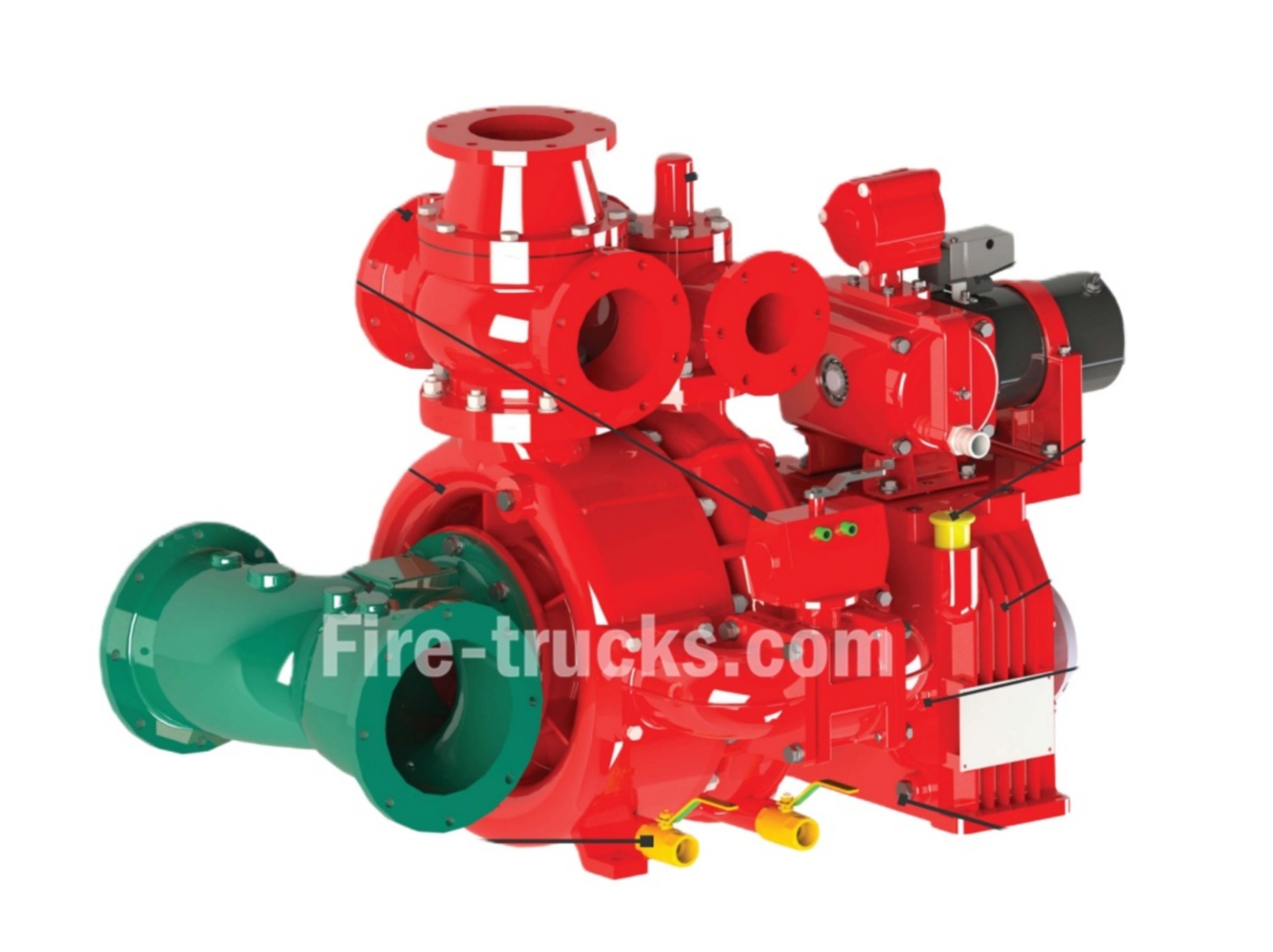
As a professional xiongzhen fire pump manufacturer in china, Powerstar Trucks owns its own brand "Xiongzhen" series of products, including low-pressure fire pump, medium-low-pressure fire pump, and high-low-pressure vehicle-mounted fire pumps, as well as supporting equipment such as fire monitors and foam proportioners. Its fire pumps utilize new materials such as aluminum alloy and stainless steel, and are equipped with an electromagnetic clutch automatic disengagement device and a check valve, featuring excellent performance, simple operation, and convenient maintenance. The company's products have passed type testing by the National Fire Equipment Quality Supervision and Inspection Center, CCC certification, and ISO9001 quality management system certification. Xiongzhen fire pumps mainly include the following models: CB10/20-XZ, CB10/30-XZ, CB10/40-XZ, CB10/60-XZ, CB10/80-XZ, CB10/100-XZ, CB20.10/15.30-XZ, CB20.10/20.40-XZ, CB20.10/30.60-XZ, etc. FIRE PUMP CB10/20-XZ for fire trucks FIRE PUMPS CB10/30-XZ for fire trucks Fire pumps Model CB10/40-XZ for fire engine China Fire pumps Model CB10-60 for fire rescue trucks Emergency Fire Pumps CB10/80-XZ for fire engine trucks fire fighting Pumps CB10/100-XZ for fire vehicle xiongzhen Fire Pump System CB10/100-XZ Specification xiongzhen CB series Fire Pump Manufacturers Fire Pumps Sets CB10/150 Specifications Fire Fighting Pump System CB10/160-XZ xiongzhen factory Emergency Fire Pumps CB10/170-XZ specifications Powerstar trucks boasts strong technical capabilities, holding four patents, and utilizes advanced production equipment such as CAD drafting and CNC machine tools to ensure high product qualification rates and customer satisfaction. Its products are primarily targeted at fire truck modification plants and fire brigades. CB20.10 20.40 fire pump details specificaiton Fire Pump CB20.10 30.60-XZ by xiongzhen factory Fire pump CB20/15-XZ series emergency fire pump CB20/20-XZ series Fire Pump Installation CB20 25 details Here's a maintenance schedule for your XIONGZHEN fire pumps, categorized by week, month, quarter, and year for easy reference: 01, Powersar Fire pump Daily Inspection: Check the start-stop pressure and frequency of the pressure-stabilizing pump. Check the starting battery power of the diesel engine fire pump. Check the appearance of the water source control valves and alarm valve assemblies for damage. 02, Powersar Fire pump Weekly Inspection: Test run the automatic start motor fire pump. Check the fuel level of the diesel engine fire pump. 03, Powersar Fire pump Monthly Inspection: Test run the manual start motor fire pump and diesel engine fire pump. Check the water level of the fire water tank and elevated fire water tank. Check the air pressure, water level, and effective volume of the pressure tank. Check t...
Details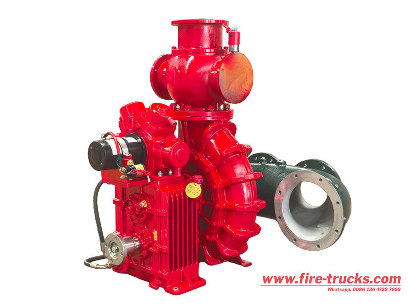
The CB10/140 foam fire fighting pump is a commonly used vehicle-mounted or stationary fire water supply system with a rated pressure of 1.0 MPa and a rated flow rate of 140 L/s, meeting the core water supply needs of firefighting systems. The pump body and impeller are constructed of high-quality, wear-resistant materials, offering corrosion resistance and high-pressure resistance. It features a dual-inlet design for rapid water source switching and is driven by a high-efficiency motor or diesel engine, achieving a startup response time of 30 seconds or less. With its compact design, easy maintenance, and reliable operation, the CB10/140 foam fire fighting pump is a vital piece of equipment for ensuring efficient water supply for firefighting operations. The CB10/140-XZ low-pressure truck-mounted fire pump features a single-stage centrifugal structure with an aluminum alloy pump casing and a brass impeller. It utilizes an electric four-piston water priming system with electric switching. The optional CB10/20 foam pump utilizes a pneumatic separation mechanism. This product offers excellent performance, a compact structure, simple operation, and easy maintenance. The CB10/140-XZ fire pump is a single-stage centrifugal water pump used in fire trucks, characterized by its two-piston priming device that automatically engages and disengages. It is designed for high performance with a compact structure, easy operation, and convenient maintenance. Key specifications include a flow rate of \(140\) L/s and an outlet pressure of \(1.0\) MPa at a rated speed of \(2600) r/min. ». Working principle of CB10/140 foam fire fighting pump ●Water and foam concentrate intake: Water is drawn from a supply, and foam concentrate is drawn from its storage tank. ●Proportioning: The proportioner mixes the foam concentrate with the water at a predetermined ratio. ●Pressurization: The pump pressurizes the mixture, increasing its velocity and pressure. ●Discharge: The pressurized foam solution is pushed through the discharge hose to the nozzle, where it is discharged onto the fire. ●Fire suppression: The foam blankets the fuel source, separating it from oxygen and extinguishing the fire. ». Detailed introduction of CB10/140 foam fire fighting pump 1. Superior Structural Design, Stable and Reliable Performance: ●The CB10/140 fire pump features a single-stage centrifugal design and is constructed from high-strength aluminum alloy, offering advantages such as light weight, corrosion resistance, and high-temperature resistance. ●The pump's internal structure is precision-machined, ensuring smooth flow and excellent hydraulic performance. A mechanical seal prevents leaks and ensures long-term operational reliability. ●This fire pump boasts powerful suction and discharge capacities, making it suitable for a variety of medium- and large-sized firefighting vehicles and emergency firefighting equipment. 2. Easy Oper...
Details
Please subscribe latest fire trucks news, and Warmly welcome to tell us what you think.

 IPv6 network supported
Links :
ISUZU Trucks
CEEC Trucks
CS Trucks
IPv6 network supported
Links :
ISUZU Trucks
CEEC Trucks
CS Trucks

 English
 français
 Deutsch
 русский
 italiano
 español
 português
 Nederlands
 العربية
 日本語
日本語 한국의
한국의 Türkçe
 Melayu
 ไทย
ไทย Tiếng Việt
 Indonesia
  中文
中文 қазақ
қазақ Filipino
 မြန်မာ
 српски