Leave A Message
If you are interested in our products and want to know more details,please leave a message here,we will reply you as soon as we can.
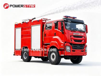
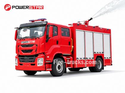
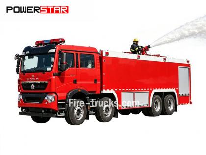
Isuzu 6HK1 Fire Rescue Vehicles, also named Isuzu fire service truck, If a Isuzu rescue fire truck engine overheats, the following areas should be checked first:1. Cooling system: Problems such as a damaged fan, clogged radiator, damaged thermostat, or insufficient coolant can all contribute to engine overheating.2. Oil quality and quantity: Poor oil quality or insufficient oil can also cause engine overheating.3. Mechanical failures such as cylinder blowout, cylinder liner cracks, or cylinder liner cracks can also cause this phenomenon.
As a heavy-duty diesel powertrain, the Isuzu 6HK1 engine requires strict adherence to technical specifications for maintenance. Key points are as follows:


1. Structural Understanding and Disassembly and Assembly Specifications
Crankshaft-Connecting Rod Mechanism
The cylinder liner features a loose-fit design, requiring special tools to prevent it from falling out during disassembly and assembly. The standard clearance is 0.122–0.156mm.
The piston outer diameter has a tight tolerance (114.894–114.909mm). During installation, pay attention to the piston ring opening direction and the "three clearances" (end clearance, side clearance, and back clearance) adjustment.
The lower crankcase is a one-piece structure and must be hoisted during maintenance to prevent deformation.
Timing System Alignment
During gearbox assembly, align the crankshaft gear and idler gear marks. The camshaft B mark must be flush with the cylinder head surface. The engine should be at compression top dead center on the first cylinder.
When installing the fuel injection pump, align the timing pointer with the S point on the connector, and align the injection advancer mark with the pump body pointer.


2. Key System Maintenance Points
Lubrication and Cooling System
Oil change interval: Mineral oil: every 5,000 kilometers or six months; synthetic oil: 8,000–10,000 kilometers.
The cooling water inlet is a stepped design and requires disassembly in sequence for maintenance. Antifreeze should be changed every two years or 40,000 kilometers.
Fuel and Air Intake System
Replace the diesel filter every 20,000 kilometers or when the warning light illuminates. Check the air filter every 15,000 kilometers.
The fuel system requires regular cleaning to prevent impurities from affecting injection accuracy.
3. Maintenance Procedure and Precautions
Tool and Data Preparation
Use a torque wrench to tighten bolts (such as the injection pump bracket bolts) according to the manual specifications.
Before repairing, consult the "4HK1-6HK1 Engine Service Manual" (page 332) for detailed parameters.
Fault Diagnosis Logic
First check the status of the "three filters," then troubleshoot the electronic control system (such as the ECU signal). Wear parts should be replaced according to the "Three Stages of Friction" theory.

4. Maintenance Interval Recommendations
Daily Maintenance: Check the engine oil and filter every 5,000 kilometers, and perform a comprehensive inspection every 10,000 kilometers.
Intensive Maintenance: Clean the fuel system and replace the transmission and axle oil every three years or 90,000 kilometers.


You may be interested in the following information
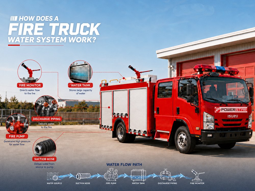
The fire truck water plumbing system is the core of every firefighting operation. It precisely directs water from the tank or an external source through the pump, valves, and piping to deliver high-pressure water or foam to the fire scene — whether it is a high-rise building fire in a dense city center or a petrochemical storage tank fire in an industrial zone. The fire truck water plumbing system consists of multiple components working together: fire pump, water tank, suction hose, discharge piping, valves, dividing breaching, collecting breaching, strainer, fire monitor, hose couplings, and more. The complete flow path is: Water Tank → Suction Hose → Strainer → Fire Pump → Pressure Regulation System → Discharge Manifold → Valves → Dividing Breaching → Fire Monitor / Hose Couplings → Nozzle This article explains each component of the water plumbing system and how they work together to deliver water at the right pressure and flow. I. Core Components of the Water Plumbing System Water Tank Stores onboard water supply. ● Capacity: Typically 2,000–12,000 liters. ● Delivery: Feeds the pump through intake piping. ● Features: Anti-slosh baffles for vehicle stability, strainer to filter debris, and priming system for drafting from natural water sources. Fire Pump A centrifugal pump driven by the truck engine through PTO; single/multi-stage, cast iron or bronze. ● Pressure grades: Available in standard ratings of 0.8 MPa, 1.0 MPa, 1.2 MPa, and 1.4 MPa, matching typical firefighting requirements. ● Flow rates: Ranges from 1,200 to 6,000 L/min, with performance curves optimized for both high-pressure and high-volume operations. Valves and Piping A network of pipes and valves that controls the direction and volume of water flow. ● Intake valve: Connects the pump to external water sources (hydrant or drafting point) ● Tank-to-pump valve: Allows the pump to draw water directly from the onboard tank ● Discharge valves: Control water flow to hoses and nozzles II. How the Fire Truck Water Plumbing System Works Step 1: Water Intake and Priming Water enters the system from the onboard tank, fire hydrant, or natural water sources (lakes, rivers, ponds). When drafting from natural sources, the priming system (vacuum pump) removes air from the suction hose, creating a vacuum that allows atmospheric pressure to push water into the pump. A strainer filters debris to protect the pump, and a check valve prevents backflow. Step 2: Pump Pressurization The centrifugal pump is driven by the truck engine through a power take-off (PTO). Once water fills the pump, the impeller spins at high speed (1,500–2,500 RPM). Centrifugal force throws water outward, increasing its velocity. The pump casing converts this velocity into pressure (typically 0.8–1.2 MPa). An electronic pressure governor automatically maintains the set pressure, while a relief valve prevents over-press...
Details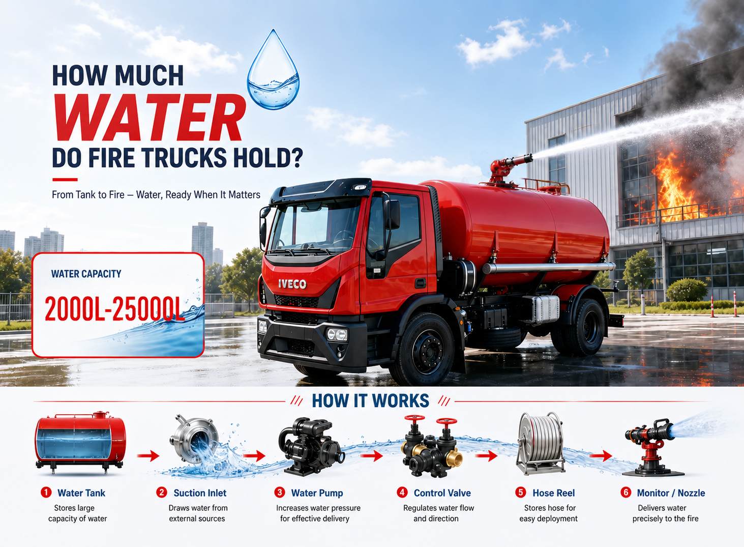
How much water can a fire truck carry? This is one of the first questions our customers face when selecting a fire truck. There is no single fixed number — it depends on vehicle type, chassis capacity, design purpose, and regional regulations, ranging from 2,000 liters light-duty units to 25,000 liters industrial fire trucks. But a larger tank does not always mean better performance; fire fighting vehicle water tank capacity must be properly matched with pump flow rate, monitor discharge rate, and chassis capacity to deliver effective firefighting results. This article starts with the fundamentals of fire truck water tank capacity, analyzes typical storage ranges for different vehicle types, examines the key factors that influence tank design, and provides practical purchasing guidance. Key Takeaways: Fire truck water tank capacity typically ranges from 2,000 to 25,000 liters Different fire truck types have different tank capacities A larger tank does not mean better firefighting capability Tank capacity must be matched with pump flow, monitor flow, and chassis capacity Industrial firefighting typically requires large tanks, while municipal firefighting prioritizes maneuverability » I. Three Basic Fire Truck Water Tank Types Pumper Trucks: These are the most common municipal fire trucks. They rely primarily on fire hydrants for water supply and carry approximately 1,900–3,800 liters of onboard water for initial attack. The core of these vehicles is the pump, not the tank — they are designed to deliver pressurized water once connected to a hydrant. Tanker Trucks (Water Tenders): These vehicles are dedicated to transporting large volumes of water, with tank capacities typically exceeding 11,400 liters. They play a critical role in rural and remote areas where fire hydrants are not available, shuttling water from water sources to the fire scene for pumpers to use. Pumper-Tankers: These vehicles combine pumping and water transport functions in one unit. They can both discharge water for firefighting and supply other vehicles. Tank capacities typically range from 5,700 to 11,400 liters, making them a versatile solution for fire departments. » II. How Much Water Can Different Types of Fire Trucks Carry? Fire Truck Type Typical Tank Capacity Primary Application Light-duty fire truck 2,000–3,000 L Urban quick response, initial attack Municipal pumper 3,000–6,000 L Municipal firefighting, structural fires Medium-duty pumper 6,000–10,000 L Combined urban and industrial tasks Heavy-duty pumper 10,000–15,000 L Extended operations, long-distance response Industrial fire truck 15,000–25,000 L Oil, chemical, mining firefighting » III. How Does a Fire Truck Water System Work? A fire truck is not just a mobile water tank — it is a complete water delivery system. Water stored in the tank must pass through several key components before it can reach the fire. Th...
Details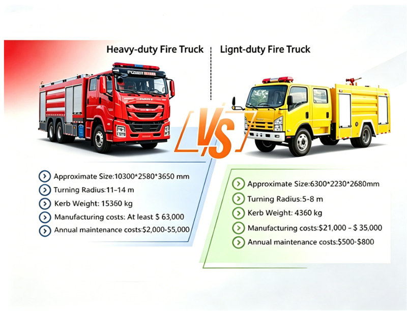
Fire rescue truck needs vary drastically between metropolitan areas and rural or small-town communities. Large urban fire departments rely on heavy duty fire trucks with massive water tanks, high rise ladders, and full industrial-grade configurations to handle high rise fires, industrial blazes, and large-scale emergencies. However, for small cities, rural towns, village fire stations, and volunteer fire departments, heavy fire trucks often become more of a burden than an advantage. This is why light fire trucks have become the mainstream and most practical solution for small city and rural fire departments worldwide. Balancing compact size, flexible mobility, complete basic rescue functions, and low overall costs, they perfectly match the daily rescue and fire prevention needs of grassroots fire teams. The light fire truck is a compact, lightweight emergency fire vehicle designed specifically for grassroots, suburban, and rural fire scenarios. I. Comparison between heavy duty fire trucks and light duty fire trucks: To clearly view the gap between heavy-duty and light fire trucks, we’ve prepared a direct comparison chart covering core practical metrics. Heavy models stretch over 10 meters with a 11–14m turning radius and 15 ton curb weight, costing at least $63,000 to build plus $2,000–$5,000 in yearly upkeep. By contrast, compact light fire trucks cut dimensions nearly in half, weigh only 4,360 kg, start at $21,000, and keep annual maintenance under $800, delivering far better mobility and budget value for rural & small-town stations. Ⅱ.Key highlights of light truck fire trucks: 1. Lightweight yet high-load bearing design. The total gross vehicle weight stays under 8,000 kg even when fully loaded, enabling ultra-fast emergency response. 2. All wheel drive customization is available to tackle rough, uneven road surfaces common in remote regions. 3. Full-spectrum firefighting functionality is fully retained: a. Dual independent tanks for water and fire suppression foam. b. Double-row crew cab to accommodate a full team of responding firefighters. c. Complete standard inventory of emergency rescue firefighting tools. d. Optional add-ons including scene lighting systems and towing equipment. 4. The power take-off (PTO) system serves as the core operation drive. It features intuitive controls and simple maintenance & component replacement. Durable core components cut long-term emergency operation expenses for rural and township fire departments significantly. Ⅲ.The following are the most popular light duty fire truck models: Chassis Model HOWO 1880 Drive system RHD/LHD, 4x2/4x4 can be optional Engine power 160HP Kerb weight 4350kg Capacity 3CBM water tank +1.5CBM foam tank Fire pump CB10/40 Fire cannon PL48 Working range 55m Chassis Model ISUZU NPR 700P Drive system RHD/LHD, 4x...
Details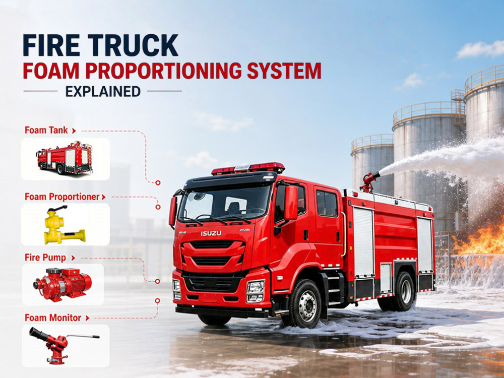
The fire truck foam system mixes water with foam concentrate at precise ratios (1%, 3%, or 6%) to create a foam solution. This solution is then pressurized by the fire pump and expanded with air through foam nozzles — this is the core working principle of how a foam fire truck mixes foam and water — ultimately producing a stable foam blanket that covers the fuel surface. This process increases firefighting efficiency by over 50% while reducing foam concentrate waste by 30%. » I. Why Does a Fire Truck Need a Foam System? Compared to using water alone, foam offers three key advantages: 1. Oxygen Isolation — Foam covers the burning surface, forming a dense physical barrier that prevents oxygen from reaching the combustion zone, thereby suppressing the fire. 2. Temperature Reduction — The water content in the foam solution absorbs large amounts of heat as it evaporates, rapidly reducing the temperature of the burning area. 3. Re-ignition Prevention — The foam layer continues to cover the fire area even after extinguishment, effectively isolating oxygen and flammable vapors, significantly reducing the risk of re-ignition. » II. Core Working Principles of the Foam System 1. Proportioning System: Water flows through the proportioner → creates negative pressure (negative pressure system) or uses a foam pump (positive pressure system) → draws foam concentrate from the foam tank → mixes at preset ratio (1%, 3%, or 6%) → foam solution flows to the pump. 2. Pump Pressurization: The foam solution enters the centrifugal pump → pressurized to 0.8–1.2 MPa → delivered through piping to discharge outlets or the foam monitor. 3. Foam Expansion: The pressurized foam solution passes through a foam nozzle or aerating device → air is entrained → the solution expands into finished foam → covers the fuel surface → cuts off oxygen and suppresses the fire. Key Concept: Foam concentrate + water does not equal finished foam. The mixed foam solution is still a liquid — it must be combined with air through a foam nozzle to become true firefighting foam. When the high-pressure foam solution passes through the nozzle at high speed, it creates a localized negative pressure zone that forcibly draws in air. The air and liquid collide and shear violently inside the nozzle, instantly breaking down into millions of tiny bubbles that accumulate to form white foam. » III. How Does a Fire Truck Mix Foam and Water? The foam mixing process on a fire truck consists of four main steps, from water supply to final foam formation. Step 1: The Fire Pump Provides Water Flow After the fire truck is started, the fire pump provides power for the foam system. Water sources can include the onboard tank, fire hydrant, rivers, lakes, or reservoirs. The fire pump is responsible for building water pressure, providing stable flow, and pushing water into the foam propor...
Details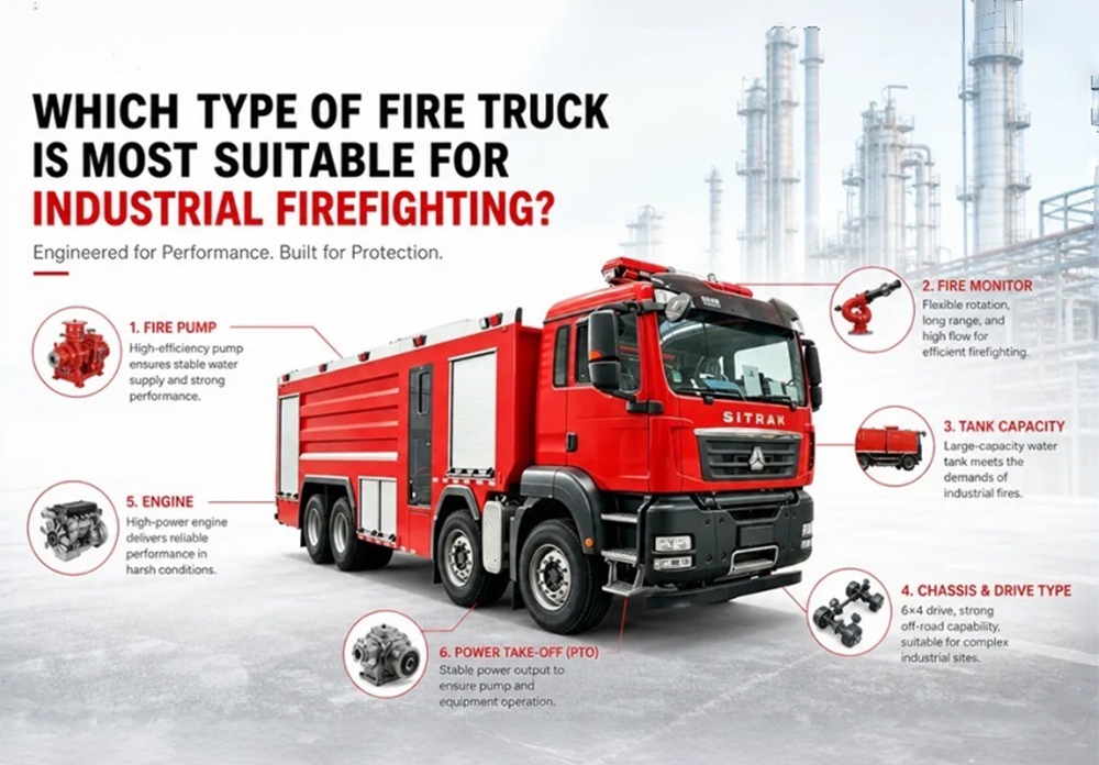
Industrial fires are fundamentally different from ordinary structural fires. Petrochemical plants primarily face flammable liquid and combustible gas fires, while manufacturing facilities and warehousing logistics centers more often deal with ordinary combustible materials — this is why different types of industrial fire trucks are required for different fire risks. This article compares water fire trucks, foam fire trucks, dry powder fire trucks, and combination units. This comprehensive buying guide helps procurement managers, engineers, distributors, and contractors understand the key differences between industrial fire truck types and select the most suitable vehicle for their specific industrial firefighting needs. » I. Quick Answer: Which Fire Truck Is Best for Industrial Firefighting? Selection should be based on fire type, industry characteristics, and extinguishing requirements: Industry Recommended Fire Truck Reason Petrochemical Water + Foam + Dry Powder Combination Unit Covers Class A, B, C, and electrical fires; adapts to complex fire scenarios Natural Gas / LNG Dry Powder Fire Truck Fast knockdown on gas fires; reduces re-ignition risk General Manufacturing Water Fire Truck Lower cost; suitable for Class A fires; simple maintenance Warehousing & Logistics Foam Fire Truck Can handle both ordinary combustibles and some liquid fires Power Plant Dry Powder + Foam Fire Truck Meets both electrical equipment and oil fire suppression needs Mining 6x4 Water Fire Truck High load capacity; good off-road capability; suitable for rough terrain In simple terms: General industrial facilities: A water fire truck is usually sufficient. Petroleum and chemical industries: A foam fire truck is the first choice. Special industries (natural gas, electrical equipment): A dry powder fire truck is recommended. Large integrated industrial parks: A water + foam + dry powder combination unit provides the most comprehensive firefighting capability and is the most versatile choice. » II. Understanding Industrial Fire Risks Before selecting a fire truck, buyers must understand the fire hazards present at their facility. Industrial fires are classified by the type of fuel involved. Fire Classifications for Industrial Settings Fire Class Fuel Type Examples Extinguishing Agent Required Class A Ordinary combustibles Wood, paper, cloth, rubber, plastics (solid materials) Water, foam, dry powder Class B Flammable liquids Gasoline, oil, diesel, chemicals, solvents Foam, dry powder, CO2 Class C Flammable gases Methane, propane, hydrogen, natural gas Dry powder, gas interruption Class D Combustible metals Magnesium, titanium, sodium, aluminum powder Specialized dry powder only Electrical Energized equipment Transformers, switchgear, power lines Dry powder, CO2 (non-conductive) Key insight: Most industrial facilities face Class B (flammable liquids) and Class C (gases) as their primary risks. This is why water-only fir...
Details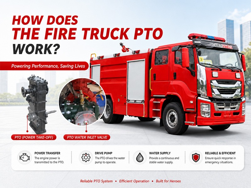
The fire truck PTO (Power Take-Off) is a power transmission device that transfers engine power to the fire pump. When the firefighter activates the PTO, mechanical power from the engine is transmitted through the transmission and PTO to the fire pump — this is the core working principle of how a fire fighting truck PTO system operates — enabling the pump to deliver high-pressure, high-flow water or foam without the need for a separate auxiliary engine. Modern fire trucks typically use side-mounted PTO or full power PTO systems. These offer stable power output, convenient operation, and low maintenance costs, making them an essential component of the fire truck's firefighting system. » I. What Is a Fire Truck PTO? 1. PTO Definition PTO (Power Take-Off) is a critical component in the fire truck's power system. It is a gear transmission device installed between the engine and the transmission, designed to "divert" a portion of mechanical power from the vehicle's engine or transmission to the fire pump or other auxiliary equipment, without affecting the vehicle's normal driving capability. The fire truck engine is originally responsible only for driving the wheels. However, once the fire truck arrives at the fire scene, the wheels no longer need power, while the fire pump requires power to draw and pressurize water. The PTO is the device that accomplishes this "power switch." 2. What Does Power Take-Off Mean? Power Take-Off (PTO) literally means "power output device." On a fire truck, it refers to extracting rotational power from the engine flywheel or transmission gears through gear engagement, and delivering it to the fire pump or other auxiliary equipment. Its name describes its function: Engine = Power source PTO = Power distributor Fire pump = Power consumption end Therefore, the PTO is the bridge connecting the "power source" and the "firefighting system." » II. Why Does a Fire Truck Need a PTO? The core reason fire trucks must be equipped with a PTO is that firefighting operations require continuous, stable, high-power output that cannot rely on the vehicle's driving state. Main reasons: 1. Provides continuous firefighting power The fire pump needs to run for extended periods during firefighting operations. The PTO allows the engine to continuously drive the fire pump at idle or fixed RPM, ensuring stable water pressure and flow. 2. Improves power utilization efficiency Without a PTO, a separate auxiliary engine would be required to drive the fire pump, which would increase: Cost Maintenance complexity Risk of failure Space occupation The PTO directly utilizes the vehicle's engine power, improving overall efficiency. 3. Supports multiple firefighting systems Modern industrial fire trucks may include not only water pumps but also: Foam systems Dry powder systems High-pressure water systems Remote-controlled fire monitors Without a PTO, there are only two solutions: Install a separate engine to drive the pump &r...
Details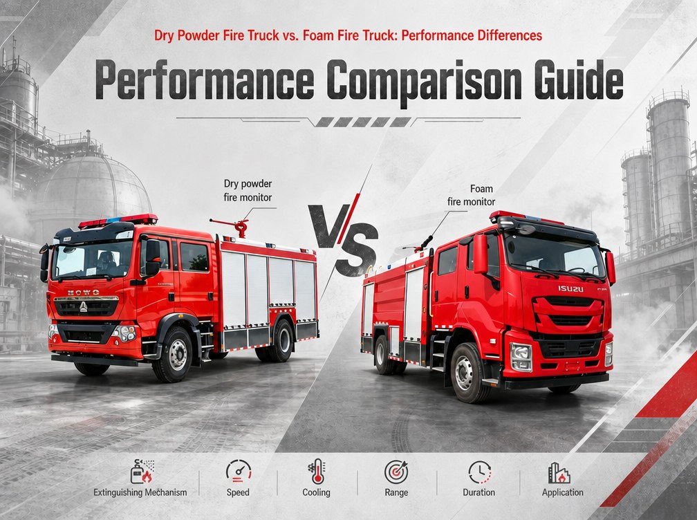
A compressed air foam system (CAFS) fire truck and a dry powder fire truck may both be used for fighting flammable liquid and gas fires. Both are specialized vehicles designed to handle Class B and Class C hazards. However, their extinguishing agents, working principles, and application scenarios are fundamentally different. This article explains the key differences between dry powder fire trucks and CAFS fire trucks from multiple perspectives: extinguishing mechanism, working principle, key components, performance parameters, application scenarios, and cost. » I. How Different Extinguishing Agents Work? 1.Why Can't Water Extinguish All Types of Fires • Class B (flammable liquids): Water is heavier than oil and sinks directly to the bottom, never reaching the flame surface. • Class C (flammable gases): Water cannot stop a gas leak; it may even spread the flame or cause a steam explosion. • Electrical fires: Water conducts electricity, creating a severe shock hazard for firefighters. • Class D (combustible metals): Water reacts violently with burning metals like magnesium, titanium, and sodium, causing explosions and spreading burning metal fragments. 2.How Does Dry Powder Work? • Chemical interruption: Dry powder particles interrupt the combustion chain reaction, stopping the fire almost instantly. • Limited cooling: Unlike water or foam, dry powder provides very little cooling effect. • No blanket: The powder does not form a lasting barrier; once it disperses, the fire may re-ignite if the fuel is still hot. • Non-conductive: Dry powder is electrically non-conductive, making it safe for electrical fires. 3.How Does Compressed Air Foam (CAFS) Work? • Blanketing: The foam covers the fuel surface, forming a dense physical barrier that blocks oxygen supply. • Cooling: The foam contains a large amount of water; water evaporation absorbs heat, continuously carrying heat away from the fuel surface. • Vapor suppression: The foam layer prevents fuel vapors from evaporating into the air, breaking the fuel-air mixing chain. • Adhesion: CAFS foam sticks to vertical surfaces and ceilings, providing protection that water cannot achieve. » II. Main Components of Each System Dry Powder Fire Truck Component Description Powder tank Stores dry chemical powder (capacity: 2,000 - 10,000 kg) Propellant gas cylinders Store compressed nitrogen or air at high pressure (15-20 MPa) Pressure regulator Reduces gas pressure to safe operating level (1.5-2.5 MPa) Powder discharge valve Controls powder flow from tank to discharge line Hoses and nozzles Deliver powder to the fire; special nozzles prevent clogging Control panel Allows operator to pressurize tank, open valves, and control discharge Compressed Air Foam System (CAFS) Fire Truck Compone...
Details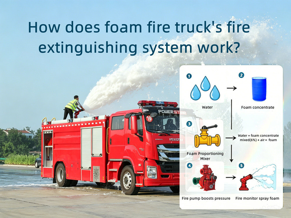
» The Underlying Logic of Foam Fire Extinguishing ★. Why can't water extinguish oil fires? • Density difference: Water is heavier than oil and sinks directly to the bottom, never touching the flame. • Boiling over: The water at the bottom vaporizes instantly upon contact with high temperatures, expanding thousands of times in volume, splattering the oil layer. • Reignition: A small amount of water evaporating into steam only temporarily isolates the oil from oxygen; once the steam dissipates, the oil surface immediately reignites. ★. How does foam work? • Isolation: The foam covers the oil surface, forming a dense physical barrier that blocks the oxygen supply. • Cooling: The foam contains a large amount of water; the evaporation of this water absorbs heat, continuously carrying away heat from the oil surface. • Blocking: The foam layer prevents oil vapor from evaporating into the air, breaking the fuel-air mixing chain. » Main components of fire extinguishing 1. Water and Liquid Supply – Two Independent Storage system The foam fire truck has two separate tanks: a water tank and a foam liquid tank. 2. Fire pump Fire pumps are the power heart of the entire fire extinguishing system, specifically designed for delivering water or foam solutions. Our fire trucks primarily use fire pumps from two well-known brands: Xiongzhen and Rongshen. Pressures include low, medium, and medium-low pressure; flow rates range from 20L/s to 180L/s; suction depth is 7m. Among them, we commonly use the CB10/60 fire pump, with a flow rate of 60L/s and a rated pressure of 1.0MPa. 3. Fire monitor Dual-purpose, capable of spraying water to extinguish solid fires and foam to extinguish oil fires; Our fire trucks primarily use Chengdu West fire monitors, which can spray water or foam liquid, and feature both spray pattern and direct current functions; they have long range, concentrated jet, high foaming ratio, and large protection area; they are flexible and convenient to operate, and the monitor body can rotate horizontally and vertically. Among them, we commonly use the PL8/48 fire monitor, with a flow rate of 48L/s and a rated pressure of 0.8MPa; the range is ≥70m for water and ≥60m for foam. 4. Water guns and foam guns Water or foam is delivered through pipes and fire hoses to the end fire guns/foam guns for fire extinguishing. 5. Fixed foam proportioner vs. fully automatic foam proportioner Comparison Dimensions Fixed Proportioning (Circulating Pump Type, Negative-Pressure) Variable- Proportioning (Circulating Pump Type, Negative-Pressure) Mixing ratio 6%(example:PH64-RS) 1%~10%,step 0.5% Work pressure range 0.6~1.4MPa 0.6~2.5MPa Flow range 16~64L/s TAF-PH120,120L/s;TAF-PH240,240L/s Proportioning accuracy Highly affected by water pressure and pipeline resistance, resulting in significant erro...
Details
Please subscribe latest fire trucks news, and Warmly welcome to tell us what you think.

 IPv6 network supported
Links :
ISUZU Trucks
CEEC Trucks
CS Trucks
IPv6 network supported
Links :
ISUZU Trucks
CEEC Trucks
CS Trucks

 English
 français
 Deutsch
 русский
 italiano
 español
 português
 Nederlands
 العربية
 日本語
日本語 한국의
한국의 Türkçe
 Melayu
 ไทย
ไทย Tiếng Việt
 Indonesia
  中文
中文 қазақ
қазақ Filipino
 မြန်မာ
 српски