Leave A Message
If you are interested in our products and want to know more details,please leave a message here,we will reply you as soon as we can.

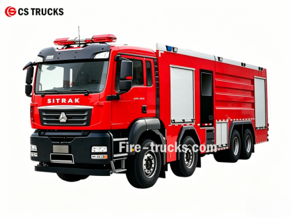
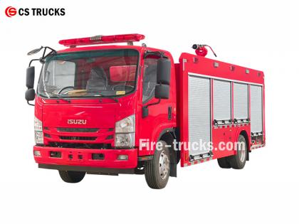
Fire trucks operate through the coordinated function of multiple systems to achieve water supply, pressure generation, and fire suppression. Understanding these principles helps fire crews operate effectively in emergency situations.

»Ⅰ. How Fire Trucks Work :
▪ A. Pump System: The Heart of Fire Suppression:
The heart of any fire truck is its pump. This high-powered unit draws water from the onboard tank or an external source—such as a fire hydrant, lake, or pond and delivers it through hoses under high pressure. The most commonly used pump is the centrifugal pump, which relies on a rotating impeller to pressurize and move water.
Firefighters control the water flow using a series of levers and gauges on the pump panel. They can adjust pressure as needed and direct water to multiple hose lines simultaneously.
|
Pump Type |
Characteristics |
Best Application |
|||
|
Single-stage centrifugal pump |
High flow, moderate pressure |
General municipal firefighting |
|||
|
Two-stage centrifugal pump |
Switchable between volume and pressure |
High-rise buildings, long hoses lay |
|||
|
Multi-stage pump |
Very high pressure |
Industrial facilities, foam systems |
|||
▪ Key Pump Parameters:
› Flow rate: 1,200 - 6,000 liters per minute (depending on model)
› Maximum pressure: 1.0 - 2.5 MPa (10-25 bar)
› Priming time: ≤30 seconds

▪ B. Water Tank and Storage System:
› Tank capacity: 500 - 1,500 gallons (approximately 2,000 to 6,000 liters), depending on vehicle size and type
› Tank material: Corrosion-resistant stainless steel or coated carbon steel
› Internal baffles: Multiple compartments with anti-surge design to control water movement during emergency response
› Filling time: ≤3 minutes via fire hydrant or drafting
› Water level indicator: Visual gauge on tank side; optional cab display
The tank is constructed from corrosion-resistant materials, typically stainless steel or coated carbon steel, with internal baffle plates that control water surge during emergency response driving.
▪ C. Hose and Nozzle Systems
Fire trucks carry various hoses with different functions:
› Attack hose: 1.5 - 2.5 inches diameter — delivers water directly to the fire source
› Supply hose: 4 - 5 inches in diameter — transports water from hydrants or other pumpers
› Booster hose: small diameter on reel — used for small fires such as grass or vehicle fires
At the end of the hose, the nozzle allows firefighters to control the water stream, adjusting pressure, pattern, and direction based on the type of fire.
▪ D. Fire Monitor
› Water monitor: Delivers high-volume water stream for large-scale fire suppression; fixed or remotely operated
› Dry powder monitor: Discharges dry chemical powder for flammable liquid, gas, and electrical fires
› Combination monitor: Capable of discharging both water and dry powder; switches between media as needed

▪ E. Engine, Powertrain and Pump Control System

Engine and Powertrain System
● Engine output: 300 - 600 horsepower — powers both vehicle mobility and fire suppression systems
● Engine type: Large diesel engine — ensures reliable performance on city streets or rough terrain under full load
● Power Take-Off (PTO): Redirects engine power to operate the water pump, aerial ladder, or other hydraulic systems

Control Panel
● Tachometer: Displays engine RPM for throttle adjustment
● Pressure gauges: Monitors low, medium, and high pressure at different discharge points
● Vacuum gauge: Shows suction pressure during drafting operations
● Liquid level indicator: Displays water tank and foam tank remaining volume
● Push-button switches & electronic throttle: Controls PTO engagement, pump start/stop, valve operation, and engine speed
» Ⅱ.Standard Operating Principles :
▪ A. Water Supply
› Tank water: Open tank-to-pump valve → Engage PTO → Set throttle → Charge hoses
› Hydrant: Connect supply hose → Open hydrant → Open intake valve → Monitor tank level
› Drafting: Position within 10m of water source → Deploy hard suction hose → Prime pump → Monitor temperature
▪ B. Firefighting Operations
› Charge attack lines at appropriate pressure
› Monitor pressure gauges
› Adjust throttle to maintain pressure
› Operate the deck
Typical pressures: Attack hose 0.7-1.0 MPa | Deck gun 1.0-1.4 MPa | Aerial 1.0-1.2 MPa gun
▪ C. Post-Fire
› Shut down discharge lines
› Disengage PTO
› Drain pump and hoses
› Refill tank
› Conduct equipment inventory
Post-fire maintenance: Flush pump, inspect hoses, check valves, document usage
» Ⅲ. Comparison of Fire Truck Types :
|
Type |
Primary Function |
Best Application |
|||
|
Water Tender |
Water supply, hose line attack |
Municipal firefighting, structural fires |
|||
|
Foam Tender |
Foam concentrate transport and proportioning |
Industrial, airport, flammable liquid fires |
|||
|
Aerial (Ladder/Platform) |
Elevated access, rescue, master streams |
High-rise fires, commercial buildings |
|||
|
Wildland |
Off-road capability, smaller tank |
Forest, brush, grassland fires |
|||
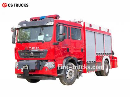
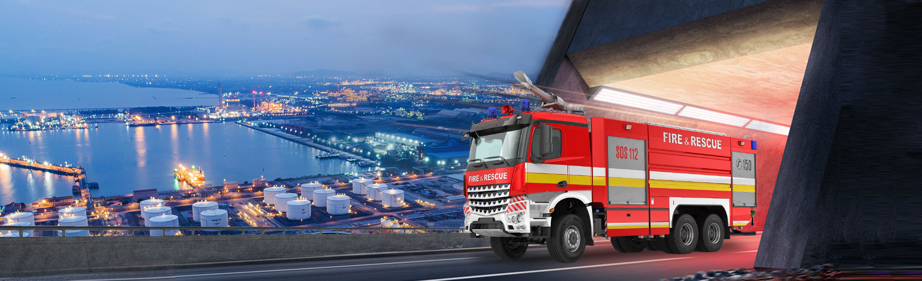
From high-rise districts to industrial zones, from highways connecting cities to rural communities, CS TRUCKS fire trucks provide reliable, efficient fire suppression and rescue solutions for diverse fire protection needs.


You may be interested in the following information
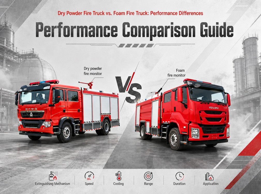
A compressed air foam system (CAFS) fire truck and a dry powder fire truck may both be used for fighting flammable liquid and gas fires. Both are specialized vehicles designed to handle Class B and Class C hazards. However, their extinguishing agents, working principles, and application scenarios are fundamentally different. This article explains the key differences between dry powder fire trucks and CAFS fire trucks from multiple perspectives: extinguishing mechanism, working principle, key components, performance parameters, application scenarios, and cost. » I. How Different Extinguishing Agents Work? 1.Why Can't Water Extinguish All Types of Fires • Class B (flammable liquids): Water is heavier than oil and sinks directly to the bottom, never reaching the flame surface. • Class C (flammable gases): Water cannot stop a gas leak; it may even spread the flame or cause a steam explosion. • Electrical fires: Water conducts electricity, creating a severe shock hazard for firefighters. • Class D (combustible metals): Water reacts violently with burning metals like magnesium, titanium, and sodium, causing explosions and spreading burning metal fragments. 2.How Does Dry Powder Work? • Chemical interruption: Dry powder particles interrupt the combustion chain reaction, stopping the fire almost instantly. • Limited cooling: Unlike water or foam, dry powder provides very little cooling effect. • No blanket: The powder does not form a lasting barrier; once it disperses, the fire may re-ignite if the fuel is still hot. • Non-conductive: Dry powder is electrically non-conductive, making it safe for electrical fires. 3.How Does Compressed Air Foam (CAFS) Work? • Blanketing: The foam covers the fuel surface, forming a dense physical barrier that blocks oxygen supply. • Cooling: The foam contains a large amount of water; water evaporation absorbs heat, continuously carrying heat away from the fuel surface. • Vapor suppression: The foam layer prevents fuel vapors from evaporating into the air, breaking the fuel-air mixing chain. • Adhesion: CAFS foam sticks to vertical surfaces and ceilings, providing protection that water cannot achieve. » II. Main Components of Each System Dry Powder Fire Truck Component Description Powder tank Stores dry chemical powder (capacity: 2,000 - 10,000 kg) Propellant gas cylinders Store compressed nitrogen or air at high pressure (15-20 MPa) Pressure regulator Reduces gas pressure to safe operating level (1.5-2.5 MPa) Powder discharge valve Controls powder flow from tank to discharge line Hoses and nozzles Deliver powder to the fire; special nozzles prevent clogging Control panel Allows operator to pressurize tank, open valves, and control discharge Compressed Air Foam System (CAFS) Fire Truck Compone...
Details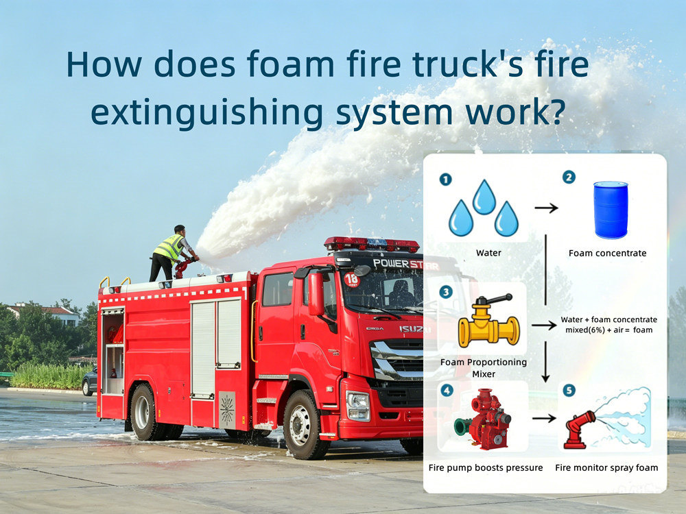
» The Underlying Logic of Foam Fire Extinguishing ★. Why can't water extinguish oil fires? • Density difference: Water is heavier than oil and sinks directly to the bottom, never touching the flame. • Boiling over: The water at the bottom vaporizes instantly upon contact with high temperatures, expanding thousands of times in volume, splattering the oil layer. • Reignition: A small amount of water evaporating into steam only temporarily isolates the oil from oxygen; once the steam dissipates, the oil surface immediately reignites. ★. How does foam work? • Isolation: The foam covers the oil surface, forming a dense physical barrier that blocks the oxygen supply. • Cooling: The foam contains a large amount of water; the evaporation of this water absorbs heat, continuously carrying away heat from the oil surface. • Blocking: The foam layer prevents oil vapor from evaporating into the air, breaking the fuel-air mixing chain. » Main components of fire extinguishing 1. Water and Liquid Supply – Two Independent Storage system The foam fire truck has two separate tanks: a water tank and a foam liquid tank. 2. Fire pump Fire pumps are the power heart of the entire fire extinguishing system, specifically designed for delivering water or foam solutions. Our fire trucks primarily use fire pumps from two well-known brands: Xiongzhen and Rongshen. Pressures include low, medium, and medium-low pressure; flow rates range from 20L/s to 180L/s; suction depth is 7m. Among them, we commonly use the CB10/60 fire pump, with a flow rate of 60L/s and a rated pressure of 1.0MPa. 3. Fire monitor Dual-purpose, capable of spraying water to extinguish solid fires and foam to extinguish oil fires; Our fire trucks primarily use Chengdu West fire monitors, which can spray water or foam liquid, and feature both spray pattern and direct current functions; they have long range, concentrated jet, high foaming ratio, and large protection area; they are flexible and convenient to operate, and the monitor body can rotate horizontally and vertically. Among them, we commonly use the PL8/48 fire monitor, with a flow rate of 48L/s and a rated pressure of 0.8MPa; the range is ≥70m for water and ≥60m for foam. 4. Water guns and foam guns Water or foam is delivered through pipes and fire hoses to the end fire guns/foam guns for fire extinguishing. 5. Fixed foam proportioner vs. fully automatic foam proportioner Comparison Dimensions Fixed Proportioning (Circulating Pump Type, Negative-Pressure) Variable- Proportioning (Circulating Pump Type, Negative-Pressure) Mixing ratio 6%(example:PH64-RS) 1%~10%,step 0.5% Work pressure range 0.6~1.4MPa 0.6~2.5MPa Flow range 16~64L/s TAF-PH120,120L/s;TAF-PH240,240L/s Proportioning accuracy Highly affected by water pressure and pipeline resistance, resulting in significant erro...
Details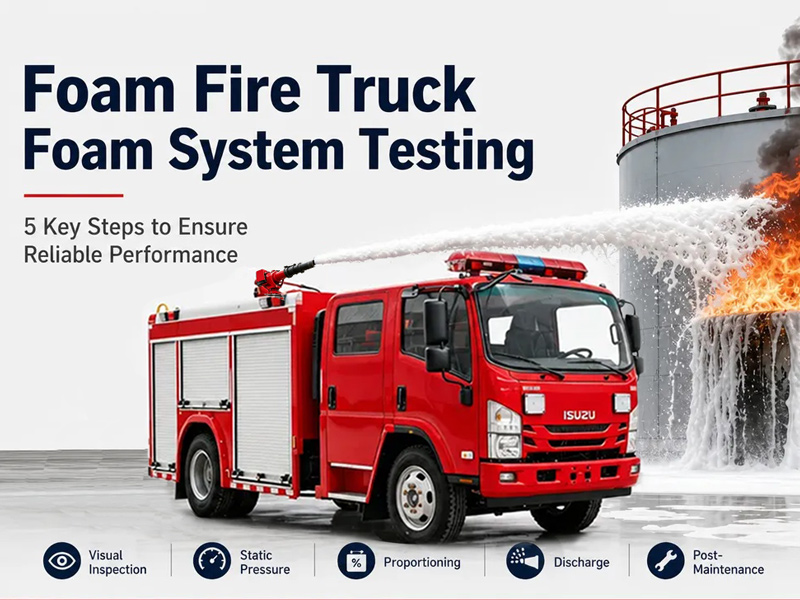
The foam fire truck is the core equipment for fighting flammable liquid fires. By precisely mixing foam concentrate with water at ratios of 1%, 3%, or 6% (accuracy ±0.5%), this foam fire truck delivers a uniform foam blanket for jet fuel fires at airports or tank fires at refineries. Its stainless steel foam tank and intelligent proportioning system ensure zero mixing errors, increasing fire suppression efficiency by over 50% while reducing foam waste by 30%. It is the invisible guardian of industrial fire safety. The core working principle and key testing procedures of the foam fire truck foam system are the focus of many customers. Let's learn about it today. 1. Three Key Components of the Foam Fire Truck Foam System 1.1 Foam tank304 stainless steel construction (4mm bottom plate, 3mm side plates), corrosion-resistant design, equipped with manhole cover, level indicator, drain port, and breather valve. 1.2 Foam proportionerInstalled in the water line, creates a vacuum as water flows through, drawing foam concentrate into the water stream. Common mixing ratios: 1%, 3%, and 6%. 1.3 Foam monitor and nozzlesRoof-mounted or handheld, 360° horizontal rotation, -30° to 80° vertical tilt, capable of producing expanded foam for fire suppression. 2. Core Working Principle of the Foam System 2.1 Proportioning systemWater flows through the proportioner → creates a vacuum → draws foam concentrate from the foam tank → mixes at preset ratio (1%, 3%, or 6%) → foam solution flows to the pump. 2.2 Pump pressurizationFoam solution enters the centrifugal pump → pressurized to 1.0-1.2 MPa → delivered through piping to the discharge outlets or monitor. 2.3 Foam expansionPressurized foam solution passes through foam nozzle → air is entrained → solution expands into finished foam → foam blanket covers fuel surface → cuts off oxygen and suppresses fire. 3. Material and Component Selection To provide customers with a more perfect foam fire truck, Fire TRUCKS selects the best materials and components for the foam system. 3.1 Foam tank system (storage and corrosion protection core) Structural Layer Material / Process Function Inner tank 304 stainless steel (4mm bottom, 3mm side) Corrosion resistance, foam concentrate compatibility Manhole cover Quick-locking mechanism Easy access for filling and cleaning Level indicator Visual gauge Real-time foam concentrate level monitoring Breather valve Pressure relief Prevents tank vacuum or overpressure 3.2 Proportioning system (mixing actuator) Foam proportioner: Installed in the water line, utilizes venturi effect to draw foam concentrate. Common ratios: 1%, 3%, 6% Control types: Manual, semi-automatic, or fully automatic Pickup line: Stainless steel or reinforced hose with strainer to prevent blockage 3.3 Discharge system (foam delivery) Foam monitor: Roof-mounted, 360° rotation, water range ≥65m, foam range ≥60m Foam ...
Details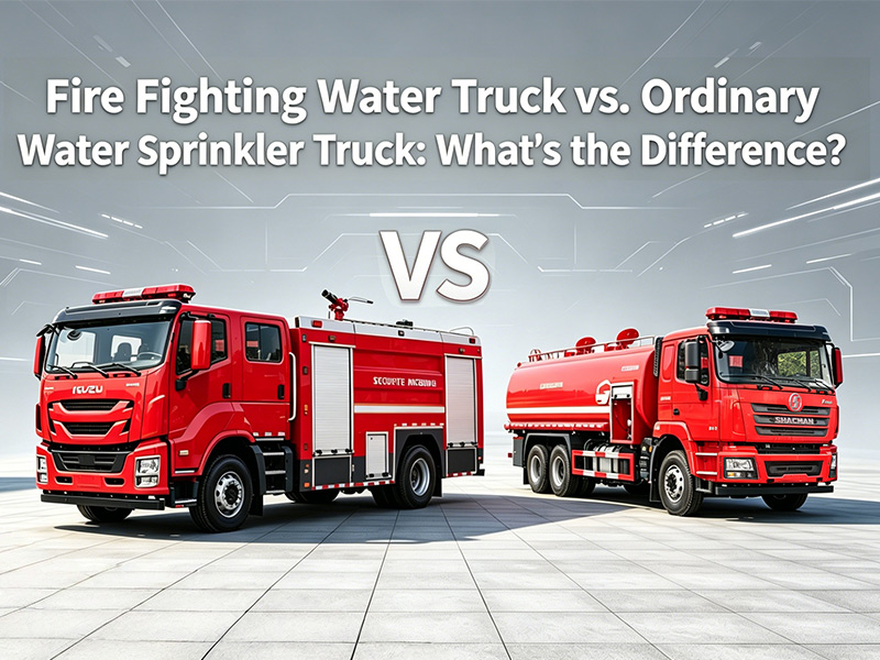
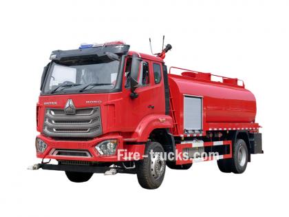
A fire fighting water truck and an ordinary water truck may look similar. Both are large vehicles with water tanks, pumps, and hoses. However, their design, components, and intended purposes are fundamentally different. This article explains the key differences between fire fighting water trucks (also known as multi-purpose water trucks or forest fire trucks) and ordinary water trucks from multiple perspectives: appearance, configuration, working principle, application, and more. » I. What Is a Fire Fighting Water Truck? A fire fighting water truck is also known as a multi-purpose water truck, forest fire truck, or fire water supply truck. It belongs to the civil fire truck series. This vehicle combines firefighting and watering functions into one unit. It sits between a professional fire truck and an ordinary water truck. Primary applications: Landscaping and green belt irrigation Firefighting and fire suppression Emergency fire water supply Dust suppression in mines and construction sites Small-scale firefighting in residential communities Pesticide spraying (optional) Key characteristics: Tank capacity: 2,000 – 12,000 liters Pump type: Fire pump driven by sandwich PTO Spray range: 50 meters or more Pump flow rate: Up to 100 cubic meters per hour Color: Fire red or engineering yellow Roof monitor: 360° horizontal rotation, -30° to 80° vertical tilt » II. What Is an Ordinary Water Truck? An ordinary water truck is a type of municipal vehicle built on a two-axle commercial chassis. It consists of an anti-corrosion water tank, a power take-off (PTO), a drive shaft, a dedicated self-priming water pump, a piping network, spray outlets, and a working platform. Primary applications: Landscaping and green belt irrigation Road maintenance and cleaning Dust suppression on construction sites Street washing Agricultural pesticide spraying (optional) Emergency firefighting (limited capability) Key characteristics: Tank capacity: 5,000 – 20,000 liters Pump type: Self-priming water pump (side-mounted PTO) Spray range: 28 meters or less Pump flow rate: Approximately 40 cubic meters per hour Color: Usually matches the chassis cab color (white is common) » III. Key Differences Between Fire Fighting Water Truck and Ordinary Water Truck 1. Appearance and Color Feature Fire Fighting Water Truck Ordinary Water Truck Body color Fire red or engineering yellow Matches chassis cab (often white) Cab marking "FIRE" or similar "SPRINKLER" or "WATER" or none Tank shape Square or circular tank with compartments Circular or rectangular tank Rear structure Pump house with roll-up doors Working platform for spray gun Top equipment Fire monitor, emergency water pipe, handrails Tank manhole cover only Warning lights Large emergency lights and siren Small clearance lights only 2. Configuration and Components Component Fire Fighting Water Truck Ordinary Water Truck PTO type Sandwich type (full powe...
Details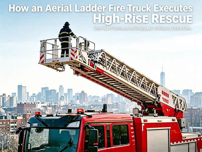
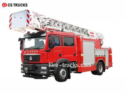
High-rise buildings present unique challenges for firefighting and rescue operations. Traditional ground-based equipment often lacks the reach needed to access upper floors from the outside. This is where aerial ladder fire trucks become indispensable. The YT25 aerial ladder fire truck, with a maximum working height of 25 meters and outreach of 15 meters, is specifically designed for such scenarios. This article explains how aerial ladder trucks perform high-rise rescue operations, using the YT25 as a technical example. » I. What Is an Aerial Ladder Fire Truck? An aerial ladder fire truck is a specialized fire apparatus equipped with a long extendable ladder mounted on a rotating turntable. Unlike standard pumpers, these vehicles are mobile platforms designed to project firefighters, equipment, and water to elevated heights. Key components of the YT25 aerial ladder truck: Component Specification Ladder 4-section synchronous telescoping truss ladder Max working height 25 m Max outreach 15 m Platform rated load 300 kg Turntable rotation 360° continuous Outriggers K-type with auto leveling » II. How High-Rise Rescue Is Performed High-rise rescue operations follow a structured sequence. Each step requires precise control and reliable equipment. Step 1: Rapid Deployment and Stabilization When a high-rise fire call is received, the aerial ladder truck responds immediately. Positioning: The crew selects a location close to the building but clear of hazards such as power lines or unstable debris. The YT25 requires adequate clearance for safe ladder operation. Outrigger deployment: The K-type outriggers extend to stabilize the truck. The YT25 features intelligent auto-leveling outriggers with a span of approximately 3.5 meters (width) and 4.8 meters (length). This creates a wide, stable base that prevents tipping during ladder extension. Time required: Outrigger leveling takes ≤30 seconds (factory standard) or as fast as 24.5 seconds (tested). Step 2: Accessing Elevated Positions Once stabilized, the aerial device is raised and extended. Reaching upper floors: The 4-section synchronous telescoping ladder can be extended to the desired floor. Full ladder operation takes ≤55 seconds (factory standard) or as fast as 41.8 seconds (tested). This speed is critical when every second counts. 360° rotation: The turntable allows continuous rotation, enabling the ladder to reach any direction around the truck without repositioning the vehicle. Step 3: Rescuing Trapped Occupants Elevated rescues often occur when building occupants cannot evacuate through stairwells or are trapped in smoke-filled areas. Platform evacuation: The YT25 is equipped with a work platform (1.34 m²) rated for 300 kg. Firefighters can guide civilians into the platform and safely lower them to the ground. The platform features: Auto-leveling system (electro-hydraulic intelligent independent leveling) Work lights and safe...
Details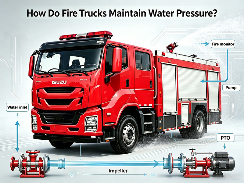
Water pressure is the driving force behind every firefighting operation. Without adequate pressure, water cannot reach the fire, penetrate burning materials, or be effective. Fire fighting trucks must not only generate pressure but also maintain it consistently throughout the entire firefighting operation. This article explains how fire trucks produce, control, and sustain water pressure, covering the key components and principles involved. » I. Where Does Water Pressure Come From? Water pressure in a fire truck comes from the fire pump. The pump is driven by the truck's engine through a power take-off (PTO) system. When the PTO is engaged, engine power is redirected to spin the pump impeller at high speed. The impeller is a rotating disc with curved vanes. As it spins, it throws water outward by centrifugal force. This action creates two effects simultaneously: Low pressure at the center (eye of the impeller): Water is drawn in from the tank or intake hose High pressure at the outer edge: Water is forced out into the discharge piping This is why most fire truck pumps are called centrifugal pumps. Pump size and power must match the vehicle's intended use. Large fire trucks, such as a 25,000-liter water/foam combination truck, require more powerful pumps to maintain high pressure while delivering large volumes of water. These heavy-duty pumps are designed for efficiency and reliability, even under extreme conditions. For smaller trucks, such as a 3,000-liter light foam pumper, a less powerful but still effective pump is used. These trucks do not need to deliver as much water, and the smaller pump is sufficient to maintain the pressure required for their operations. Additionally, the height of the onboard water tank and the position of the pump affect pressure. Water flows by gravity from the tank to the pump, but the pump must still increase the pressure to push water effectively through the hoses. » II. How Is Pressure Controlled? Once pressure is generated, it must be controlled to match the specific firefighting task. Different situations require different pressures. 1. Engine Throttle Control The simplest way to adjust pressure is by changing engine speed. Increasing engine RPM spins the pump impeller faster, which increases pressure. Decreasing RPM lowers pressure. The pump operator controls engine speed from the pump panel using an electronic throttle. 2. Pressure Governor Systems Modern fire trucks are equipped with electronic pressure governors. These devices automatically maintain the set pressure regardless of changes in flow. When a firefighter opens or closes a nozzle, the flow demand changes. Without a governor, pressure would drop when a new hose line is opened or spike when a line is closed. The governor senses these changes and automatically adjusts engine speed to keep pressure constant. Mode Function Pressure mode Maintains a preset pressure regardless of flow changes RPM mode Maintains a preset eng...
Details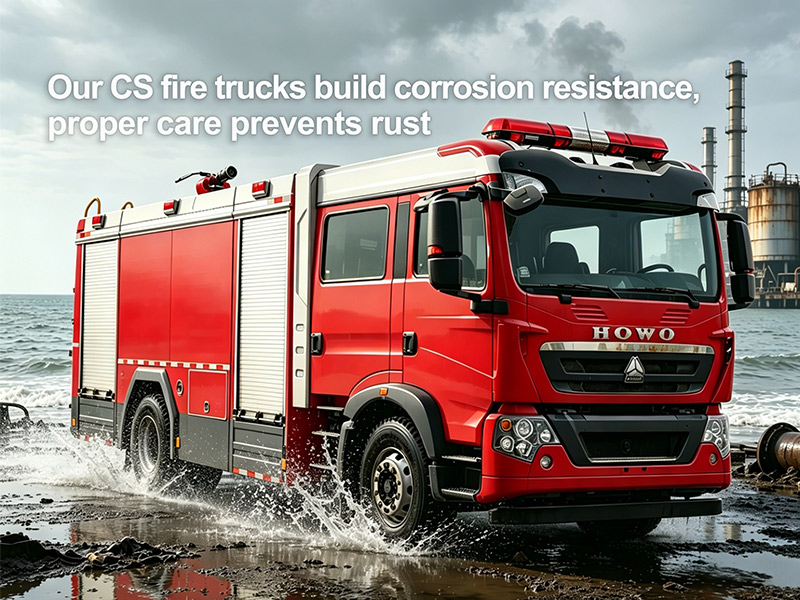
Fire trucks operate in harsh environments — humid climates, chemical spills, coastal salt spray. Without effective corrosion protection, metal components of a fire fighting vehicle rust, structures weaken, and firefighting capability drops. This article explains how rust forms, which tank materials resist corrosion best, and what coatings actually work. I. Three Common Types of Corrosion on Fire Trucks 1. Pitting Corrosion Small holes (pits) form on metal surfaces. Common on coastal fire trucks due to chloride ions in sea air. Pitting is dangerous because it penetrates deep into metal while looking like minor surface damage. 2. Crevice Corrosion Occurs in tight spaces where moisture gets trapped — under gaskets, bolts, rivets, weld seams, or between metal and rubber seals. Sand, dust, and debris accelerate it. 3. Galvanic Corrosion Happens when two different metals contact each other in the presence of moisture. The more active metal corrodes faster. Fire trucks use steel, aluminum, stainless steel, and brass — proper insulation between dissimilar metals is critical. II. Tank Materials: Which One Resists Rust Best? Material Corrosion Resistance Best For Carbon steel Low (requires coating) Budget trucks Stainless steel 304 Good Standard municipal use Stainless steel 316 Excellent (contains molybdenum) Coastal areas, chemical plants Why 316 stainless steel? The addition of molybdenum provides superior resistance to chlorides (salt water) and chemicals. For fire trucks operating near the ocean or in industrial zones, 316 is the right choice. III. Anti-Corrosion Coatings That Work For Water Tanks (Potable Water Safe) Water tanks often store water from rivers, lakes, or hydrants. This water contains chlorides and impurities that accelerate stainless steel corrosion. Internal coating is necessary. Recommended coating: H52-33 epoxy anti-corrosion paint. It is non-toxic, salt-resistant, alkali-resistant, and water-resistant. Suitable for drinking water systems and fire truck water tanks. For Foam Tanks Foam concentrate reacts chemically with some coatings. Never use epoxy asphalt coating inside foam tanks — it will break down and contaminate the foam. Use proper foam-tank-grade anti-corrosion paint instead. Coating Application Process Surface preparation: Sandblasting removes rust, oil, and dirt Primer application: Improves adhesion Intermediate coat: Builds thickness Top coat: Provides chemical resistance and UV protection Critical: If the weld gap is between 0.025-0.1mm, crevice corrosion sensitivity increases dramatically. Weld spatter destroys the passive layer on stainless steel, leading to pitting. All weld slag and spatter must be removed after welding. IV. Fastener Corrosion Protection Bolts, screws, rivets, and pins are load-bearing components. Surface treatment methods include: Treatment Corrosion Resistance (NSS Test) Application Zinc plating 120 hours no red rust Grade 8...
Details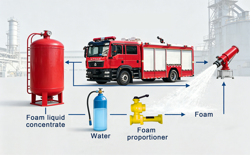
Foam fire trucks are essential for fighting flammable liquid fires at airports, oil refineries, chemical plants, and fuel storage facilities. Like all specialized equipment, foam fire trucks require regular maintenance to stay ready for emergencies. This article covers common faults and practical solutions. I. Types of Firefighting Foam Before discussing faults, understanding foam types is essential. There are three main categories: Foam Type Application Class A Foam Ordinary combustibles (wood, paper, cloth) Class B Foam Flammable liquids (gasoline, oil, diesel) AFFF (Aqueous Film Forming Foam) Forms a barrier between fuel and air, prevents re-ignition II. Common Faults and Solutions 1. Pressure System Faults Problem: Insufficient foam discharge or unstable pressure Possible causes: Damaged pressure pump Pump drive system failure Blocked pipelines Solutions: Regularly inspect the pump and drive system Clean and maintain pipelines Repair or replace damaged components 2. Foam Liquid Supply Issues Problem: Insufficient foam liquid or system not working properly Possible causes: Foam liquid pump failure Foam tank problems Blocked foam liquid pipelines Solutions: Check pump, tank, and pipelines Ensure all passages are clear Clean and replace damaged components 3. Control System Faults Problem: Unable to accurately control foam discharge and water flow Possible causes: Circuit failure Damaged control panel Sensor failure Solutions: Check circuit connections Replace damaged control panel or sensors Perform system recalibration 4. Foam Concentration Control Issues Problem: Foam concentration too high or too low, affecting extinguishing performance Possible causes: Concentration control system failure Damaged proportioner Incorrect proportioner settings Solutions: Calibrate the concentration control system Inspect and clean the proportioner Ensure foam concentration is within the correct range 5. Vehicle Power System Faults Problem: Vehicle power system failure affects driving and operation Possible causes: Engine failure Transmission problems Electrical system failure Solutions: Regularly inspect engine, transmission, and electrical system Ensure normal operation Repair or replace faulty components in a timely manner 6. Foam Generator Cannot Produce Foam Problem: Foam generator fails to produce foam or produces poor quality foam Possible causes: Air inlet blocked by foreign objects Foam mixture does not meet requirements (expired foam concentrate, incorrect proportioning ratio) Solutions: Inspect and remove blockages from the air inlet Test and maintain the proportioner Replace expired foam concentrate 7. Proportioner Corrosion or Seizure Problem: The proportioner is rusted or stuck Possible causes: Not rinsed with clean water after use Long-term corrosion from foam concentrate Solutions: Regularly remove and maintain the proportioner Rinse thoroughly with clean water after each test or use 8. Pump Perfor...
Details
Please subscribe latest fire trucks news, and Warmly welcome to tell us what you think.

 IPv6 network supported

 English
 français
 Deutsch
 русский
 italiano
 español
 português
 Nederlands
 العربية
 日本語
日本語 한국의
한국의 Türkçe
 Melayu
 ไทย
ไทย Tiếng Việt
 Indonesia
  中文
中文 қазақ
қазақ Filipino
 မြန်မာ
 српски