Leave A Message
If you are interested in our products and want to know more details,please leave a message here,we will reply you as soon as we can.

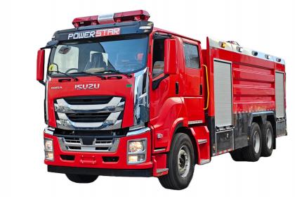
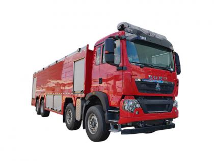
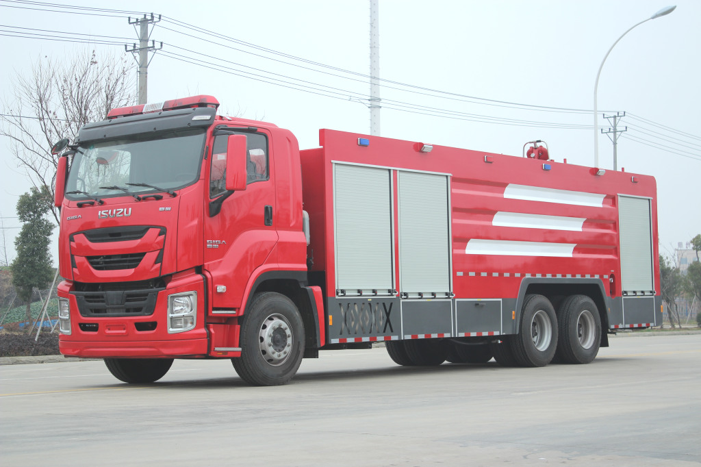
Isuzu 4,000L foam firefighting truck is engineered to combat Class B fires involving flammable liquids (e.g., petroleum, chemicals). Its foam projection system mixes water with fire-suppressing foam at precise ratios, forming an oxygen-blocking blanket to rapidly extinguish liquid fuel blazes. Equipped with a high-capacity 4,000-liter tank and a high-pressure pump, Isuzu 4,000L foam firefighting truck delivers sustained foam discharge rates up to 4,000 L/min, enabling swift control of expansive fire incidents. Its extended-range monitor nozzle projects foam over 60 meters, ensuring operator safety during refinery, warehouse, or wildfire emergencies.

Operational Guide for Isuzu 4,000L Foam Firefighting Truck: Technical Parameters and Procedures
1. Vehicle Overview
The Isuzu 4,000L foam firefighting truck is engineered for rapid response to Class B (flammable liquids) and Class A (solid combustibles) fires. Built on a heavy-duty Isuzu FVR chassis, it features a 6HK1-TCG61 diesel engine with a power output of 176 kW (240 hp) at 2,200 rpm, generating 981 N·m torque. The chassis complies with Euro V emission standards and includes a 9-speed manual transmission for optimal off-road maneuverability.
2. Firefighting System Specifications

3. Discharge Equipment
4. Control and Monitoring Systems

5. Operational Procedure
Step 1: Pre-Deployment Checks
Step 2: Engine and Pump Activation
Step 3: Foam Application
Step 4: Discharge Control
Step 5: Post-Operation
6. Safety Protocols


|
Name |
Water Foam Tank Fire Truck |
|
|
Model |
PT550PM |
|
|
Painting |
Fire red (RAL 3000) (Customer LOGO welcome) |
|
|
Chassis |
Brand |
ISUZU |
|
Chassis Model |
ISUZU GIGA 4X |
|
|
Engine power |
150KW (205HP) |
|
|
4X2 Left Hand Drive, Double Cabin |
||
|
Outline dimension |
8150×2500×3600 mm |
|
|
Gross Vehicle Weight |
18000 kg |
|
|
Number of Seats |
1+1+4 (inc. driver) |
|
|
Fire-extinguishing Agents |
Water (L) |
5000L |
|
Foam (L) |
500L |
|
|
Chemical (L) |
Without |
|
|
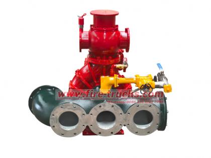
Fire pump |
Model |
XIONGZHEN CB10/40 |
|
Pressure (Mpa) |
1.0 |
|
|
Rate (L/s) |
40 |
|
|
Fire Monitor |
Model |
PL36 |
|
Rate (L/s) |
36 |
|
|
Throw Range(m) |
Water ≥ 60, Foam≥ 50 |
|
|
Fire Equipment |
Factory standard |
Special equipment for optional |


You may be interested in the following information
Resce fire vehicle with 6HK1 series engine are core power systems for commercial vehicles, and sensor failures directly impact engine performance and reliability. Common fault types include abnormal vehicle speed sensor signals leading to ECU speed limits and fuel cutoffs, coolant temperature sensor reading deviations causing cooling system disruptions, and camshaft sensor failures causing ignition sequence errors. These faults are often caused by sensor aging, poor wiring connections, or mechanical installation issues (such as insufficient torque). For example, a damaged vehicle speed sensor may cause the ECU to misinterpret an overspeed condition and cut fuel injection, resulting in a sudden loss of power at high speeds. Signal Color and diameter 1 GND B/0.5 2 SIG Y/0.5 3 Shield G/0.5 1 Measuring point Resistance (kΩ) Temperature ℃ Terminal 1 <--> Terminal 2 1.21 40 3. 25 0 Terminal 1 <--> Body Terminal 2 <--> Body Connector Terminal No. Signal Wire cotor/diameter(Injection pump harness) SWP 8-terminals Black 1 Governor actuator drive voltage - 1 RM 2 2 Governor circuit GND-1 W/1.2 3 Target rack position - 1 U1 2 4 Rack position voltage G/1.2 5 Governor circuit 5V-1 Y/1.2 6 Backup N sensor (GND) BR/1.2 7 Backup N sensor (SIG) 0/1.2 8 Pull-down B/1.2 SWP6- terminals Black g Governor actuator drive voltage - 2 R/1.2 10 Target rack position - 2 L/1.2 11 Governor circuit GND-2 W/1.2 12 Governor circuit SIG-GND BR/1.2 13 Governor circuit 5V-2 Y/1.2 SWP 3-terminalsBlack 14 Limp home W1.2 15 Sub-coil (Not used) BY/1.2 Measuring point Resistance Terminal 2 <--> Terminal 1 2,1-2.5 kΩ Terminal 2 <--> Terminal 3 ∞ Terminal 2 <-->Body ∞ Terminal 1 <-->Terminal 3 ∞ Terminal 1<--> Body ∞ Terminal 3<-->Body ∞ Diagnosis and repair of Isuzu 6HK1 series engine sensor failures require a combination of professional testing and targeted measures. For a speed sensor failure, use a fault detector to read the data stream. If the displayed speed is significantly different from the actual speed (e.g., 222 km/h when the actual speed is 80 km/h) and the fuel injection volume is zero, the sensor is considered faulty. For a coolant temperature sensor failure, use a multimeter to measure the resistance at different temperatures. If the resistance deviates significantly from the standard value or the signal is interrupted, replace the sensor and check the sealing gasket for leaks caused by insufficient torque. Camshaft sensor failure is often accompanied by fault codes P0340/P0341. Use an oscilloscope to check for missing or distorted signal waveforms. A clogged oxygen sensor will cause the signal voltage to be consistently high or low. Cleaning the through-hole or replacing the sensor is necessary to restore air-fuel ratio control. During repair, pay special attention to clearing ECU fault co...
Details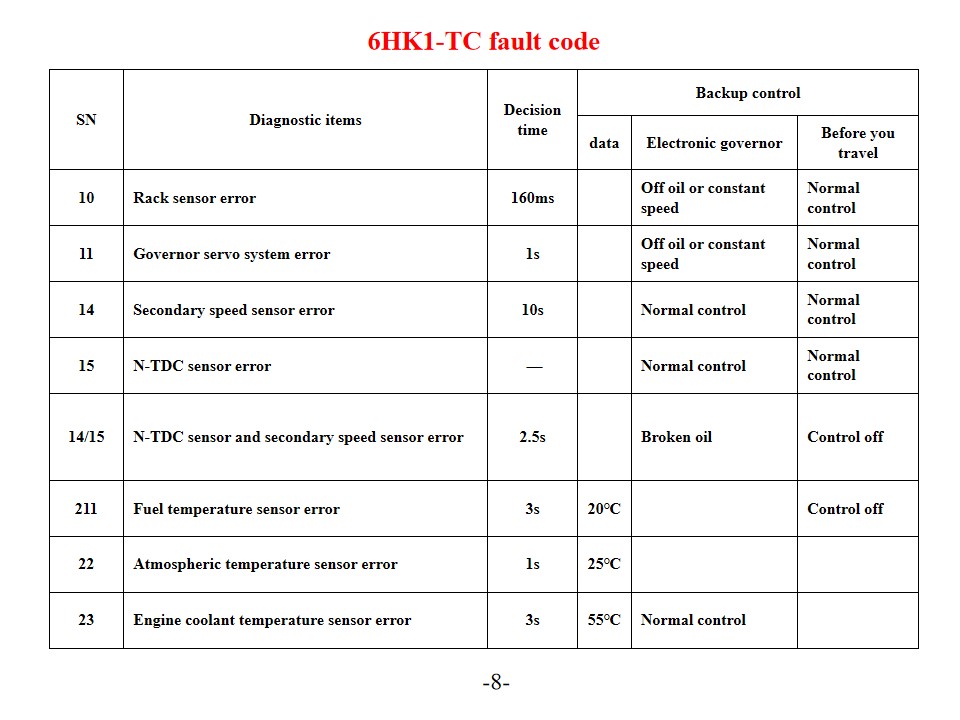
Isuzu 6HK1-TC fire trucks, also named Isuzu rescue fire vehicle, Engine Error Code Diagnosis and Solutions.The Isuzu 6HK1-TC engine utilizes the advanced TICS fuel injection pump electronic control system, and the ECU (Engine Control Unit) features self-diagnosis. When the system detects a fault, the "CHECK ENGINE" warning light illuminates and the corresponding fault code is stored. Understanding the interpretation and solutions for these error codes can effectively improve engine maintenance efficiency. Common Error Codes and Solutions P-Series Trouble Codes P0101 (Mass Air Flow Sensor Circuit Low) Check the engine coolant temperature sensor and its wiring. Verify the sensor power supply voltage and ground connection. Replace the ECU or sensor if necessary. P0102 (Mass Air Flow Sensor Circuit High) Check fuel quality and filter condition. Clean the fuel system. Check the fuel pressure regulator, fuel pump, and injector circuits. P0103 (Mass Air Flow Sensor A Circuit High) Check the sensor signal circuit for a short circuit. Test the sensor's operating status. Replace the sensor or ECU if necessary. Digital Trouble Codes 10 (Rack Sensor Error) Check the rack sensor and its wiring. Verify normal signal transmission. 11 (Speed Governor Servo System Error) Check the speed governor servo system's operating status. Test related circuit connections. 14 (Auxiliary Speed Sensor Error) Check the auxiliary speed sensor's installation position. Test the sensor's signal output. 15 (N-TDC Sensor Error) Check N-TDC sensor connection Verify signal accuracy System maintenance and preventive measures SN Diagnostic items Decision time Backup control data Electronic governor Before you travel 10 Rack sensor error 160ms Off oil or constant speed Normal control 11 Governor servo system error 1s Off oil or constant speed Normal control 14 Secondary speed sensor error 10s Normal control Normal control 15 N-TDC sensor error — Normal control Normal control 14/15 N-TDC sensor and secondary speed sensor error 2.5s Broken oil Control off 211 Fuel temperature sensor error 3s 20℃ Control off 22 Atmospheric temperature sensor error 1s 25℃ 23 Engine coolant temperature sensor error 3s 55℃ Normal control Connector Terminal No. Signal Wire cotor/diameter(Injection pump harness) SWP 8-terminals Black 1 Governor actuator drive voltage - 1 RM 2 2 Governor circuit GND-1 W/1.2 3 Target rack position - 1 U1 2 4 Rack position voltage G/1.2 5 Governor circuit 5V-1 Y/1.2 6 Backup N sensor (GND) BR/1.2 7 Backup N sensor (SIG) 0/1.2 8 Pull-down B/1.2 SWP6- terminals Black g Governor actuator drive voltage - 2 R/1.2 10 Target rack position - 2 L/1.2 11 Governor circuit GND-2 W/1.2 12 Governor circuit SIG-GND BR/1.2 13 Governor circuit 5V-2 Y/1.2 SWP 3-terminalsBlack 14 Limp home W1.2 15 Sub-coil (Not used) BY/1.2 Regular maintenance Change engine oil on schedule (base...
Details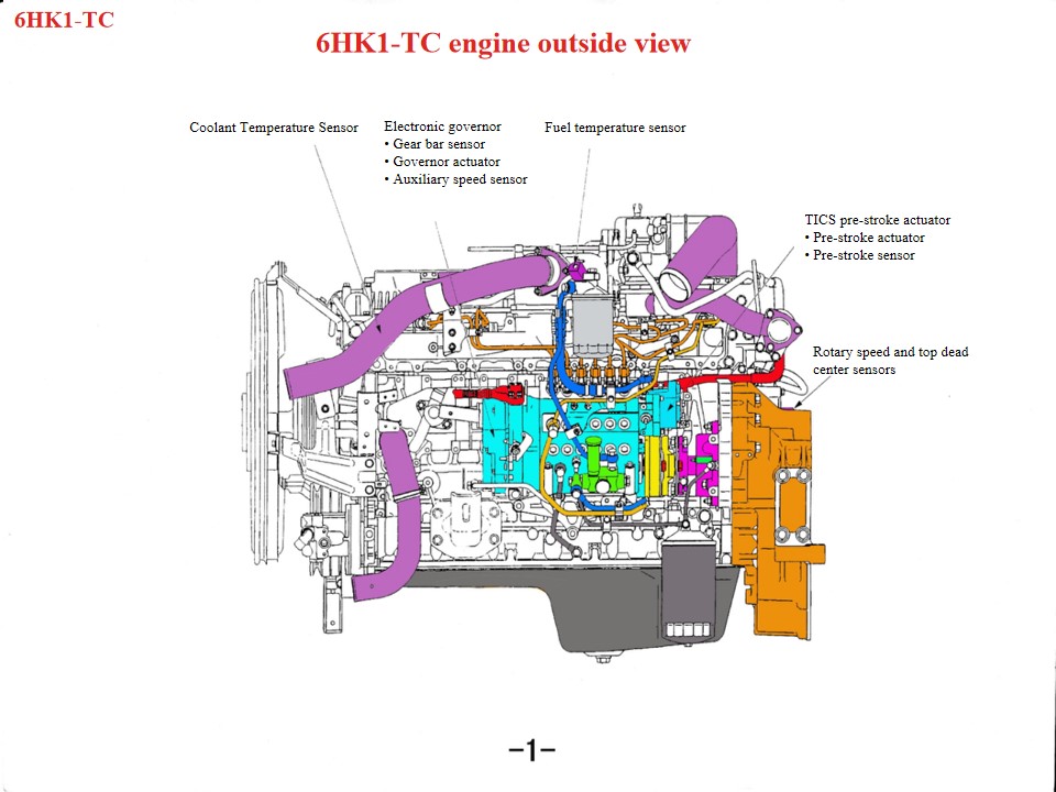
Isuzu 6HK1 Fire Rescue Vehicles, also named Isuzu fire service truck, If a Isuzu rescue fire truck engine overheats, the following areas should be checked first:1. Cooling system: Problems such as a damaged fan, clogged radiator, damaged thermostat, or insufficient coolant can all contribute to engine overheating.2. Oil quality and quantity: Poor oil quality or insufficient oil can also cause engine overheating.3. Mechanical failures such as cylinder blowout, cylinder liner cracks, or cylinder liner cracks can also cause this phenomenon. As a heavy-duty diesel powertrain, the Isuzu 6HK1 engine requires strict adherence to technical specifications for maintenance. Key points are as follows: 1. Structural Understanding and Disassembly and Assembly Specifications Crankshaft-Connecting Rod Mechanism The cylinder liner features a loose-fit design, requiring special tools to prevent it from falling out during disassembly and assembly. The standard clearance is 0.122–0.156mm. The piston outer diameter has a tight tolerance (114.894–114.909mm). During installation, pay attention to the piston ring opening direction and the "three clearances" (end clearance, side clearance, and back clearance) adjustment. The lower crankcase is a one-piece structure and must be hoisted during maintenance to prevent deformation. Timing System Alignment During gearbox assembly, align the crankshaft gear and idler gear marks. The camshaft B mark must be flush with the cylinder head surface. The engine should be at compression top dead center on the first cylinder. When installing the fuel injection pump, align the timing pointer with the S point on the connector, and align the injection advancer mark with the pump body pointer. •The linear DC motor pushes the coil up and down under the control unit output signal. •The connecting rod installed on the coil assembly transmits the up and down motion of the coil to the connecting block, and the connecting block is installed at the end of the rack. Under the push of the connecting block, the rack moves left and right to change the amount of fuel injected. When the coil assembly moves up, the link pushes the rack to increase the direction of the oil; conversely, when the coil assembly goes down, the rack moves in the direction of reducing the oil, and the function of the column is to convert the vertical motion to the height of the rack. movement. •The copper block is mounted on the upper part of the connecting block to form a rack sensor. The rack sensor detects the rack stroke and feeds this value back to the control unit so that the actual rack stroke and the target rack stroke can be continuously compared until the difference between the two approaches zero. This process is very important to control accuracy and response. 2. Key System Maintenance Points Lubrication and Cooling System Oil change interval: Mineral oil: ev...
Details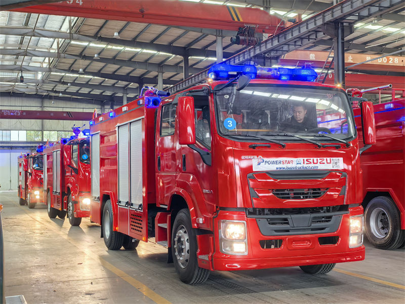
Isuzu 4,000L foam firefighting truck is engineered to combat Class B fires involving flammable liquids (e.g., petroleum, chemicals). Its foam projection system mixes water with fire-suppressing foam at precise ratios, forming an oxygen-blocking blanket to rapidly extinguish liquid fuel blazes. Equipped with a high-capacity 4,000-liter tank and a high-pressure pump, Isuzu 4,000L foam firefighting truck delivers sustained foam discharge rates up to 4,000 L/min, enabling swift control of expansive fire incidents. Its extended-range monitor nozzle projects foam over 60 meters, ensuring operator safety during refinery, warehouse, or wildfire emergencies. Operational Guide for Isuzu 4,000L Foam Firefighting Truck: Technical Parameters and Procedures 1. Vehicle OverviewThe Isuzu 4,000L foam firefighting truck is engineered for rapid response to Class B (flammable liquids) and Class A (solid combustibles) fires. Built on a heavy-duty Isuzu FVR chassis, it features a 6HK1-TCG61 diesel engine with a power output of 176 kW (240 hp) at 2,200 rpm, generating 981 N·m torque. The chassis complies with Euro V emission standards and includes a 9-speed manual transmission for optimal off-road maneuverability. 2. Firefighting System Specifications Water Tank: 4,000-liter capacity, constructed from corrosion-resistant 304 stainless steel with internal baffles for stability. Foam Tank: 500-liter polyethylene tank, compatible with AFFF (Aqueous Film-Forming Foam) or AR-AFFF (Alcohol-Resistant) concentrates. Proportioning System: Electronically controlled foam induction system with adjustable ratio (1–10%) via a rotary dial on the pump panel. Pump Unit: Mid-ship-mounted centrifugal pump (Model NH30), delivering 4,000 L/min at 1.0 MPa pressure. Maximum suction lift: 7 meters. 3. Discharge Equipment Roof-Mounted Monitor: Remote-controlled telescopic monitor with 360° rotation, 70-meter range (water), and 55-meter range (foam). Flow rate adjustable from 100–3,800 L/min. Handline Reels: Two 30-meter Class B rubber-lined hoses (Φ65 mm) with adjustable fog/straight stream nozzles (500 L/min max). Rear Bumper Reel: 20-meter high-pressure hose (Φ25 mm) for auxiliary operations (200 L/min). 4. Control and Monitoring Systems Pump Panel: Centralized interface with analog pressure gauges, tachometer, and digital foam ratio display. Includes manual override for pump RPM (0–2,500). Cabin Display: 7-inch LCD screen for real-time monitoring of water/foam levels, pump status, and engine diagnostics. Lighting: Four 500W LED floodlights (360° rotation), two rear warning beacons, and scene lighting compliant with NFPA 1901 standards. 5. Operational ProcedureStep 1: Pre-Deployment Checks Verify water/foam tank levels and inspect hose integrity. Ensure pump priming valve is closed and suction strainer unobstructed. Step 2: Engine and Pump Activation Start the chassis engine; engage PTO (Power Take-Off) to activate the pump. Graduall...
Details
Please subscribe latest fire trucks news, and Warmly welcome to tell us what you think.

 IPv6 network supported

 English
 français
 Deutsch
 русский
 italiano
 español
 português
 Nederlands
 العربية
 日本語
日本語 한국의
한국의 Türkçe
 Melayu
 ไทย
ไทย Tiếng Việt
 Indonesia
  中文
中文 қазақ
қазақ Filipino
 မြန်မာ
 српски